This “rack-mounted switch for small businesses” from Linksys (then still a Cisco subsidiary) will initially be used temporarily in our home until the network is fully set up. But even later, 48 ports with a maximum of 1 GbE* each will still be useful for a large number of devices. Fortunately, the technical data can still be found at Cisco (archive.org). The user manual is elsewhere also available.
First, the device had to be reset, cleaned, serviced, and reconfigured, as it came from a company liquidation and had been lying around for years (condition unknown). This model series is equipped with “WebView” which allows for convenient configuration via a web browser. Unfortunately, this only works in older browser versions – but at least it works.
Condition
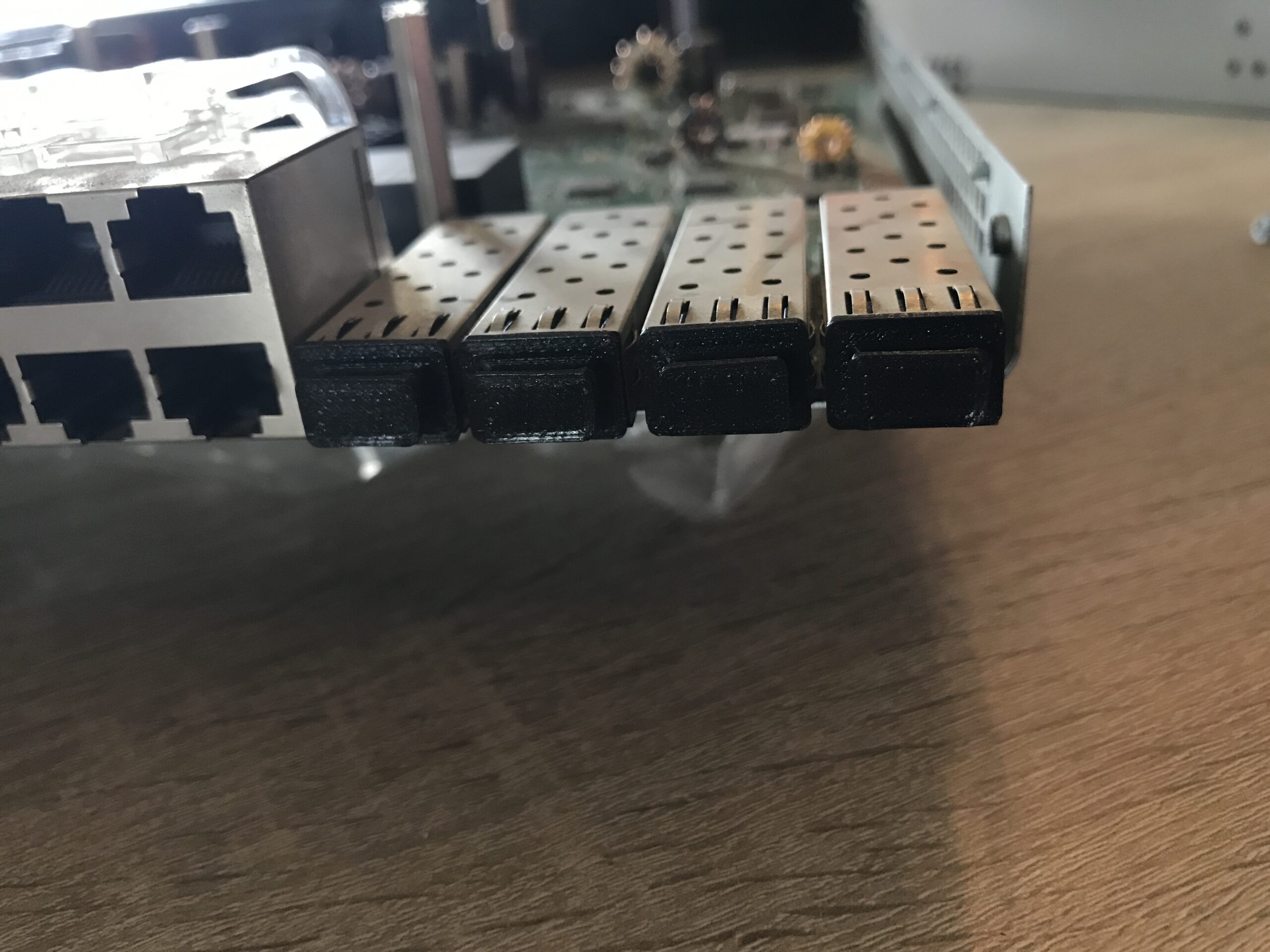
The black plastic front panel is cracked on both sides (this should be easy to repair with superglue*) and the fan(s) have audible bearing damage. After testing all 48 RJ-45 ports, they all seem to work fine with both 100 Mbit and 1 Gbit. I did not test the four SFP ports on the right-hand side due to a lack of modules but these can also “only” handle GbE and share their bandwidth with specific RJ-45 ports as labeled, so they are of little interest at the moment. I have sealed them with 3D-printed PLA caps to protect them from dust (model from Thingiverse by jbanion):
Apart from dirt and scratches, the rest of the device is in relatively good condition; there is no visible corrosion or mechanical damage to the relevant components.
Hardware
| SoC | Marvell 88E6218 (Link Street) |
| Integrated CPU | ARM946E-S (32-Bit) 1 Core / 1 Thread 133 – 150 MHz Instruction Cache: 8 KB Data Cache: 8 KB Fun Fact: The same CPU core was also used in the Nintendo DS / DSi! |
| RAM | 64 MB Mira SDRAM @ 166 MHz |
| Flash | 16 MB |
Open the device
First, the switch must be opened: this is not as easy as it sounds. The rack mounts are each secured with four PH2 screws on each side and must be unscrewed. Then, using a soft, flat tool such as a guitar pick*, the front panel must be loosened; it is pushed on all around and clipped in place. Next, use a spatula* or a similarly thin but harder tool to gently pry open the gap in the metal housing on one side first; both parts of the housing are held together with metal clips. Work carefully, as the brackets are fragile.
Once the gap has widened, you can work your way across until the entire width is detached. Then do the same on the opposite side, but this is much easier because you can push and press. Finally, pull the upper part of the housing out of the rear plastic cover. It is quite tightly fitted.
Remove the fans
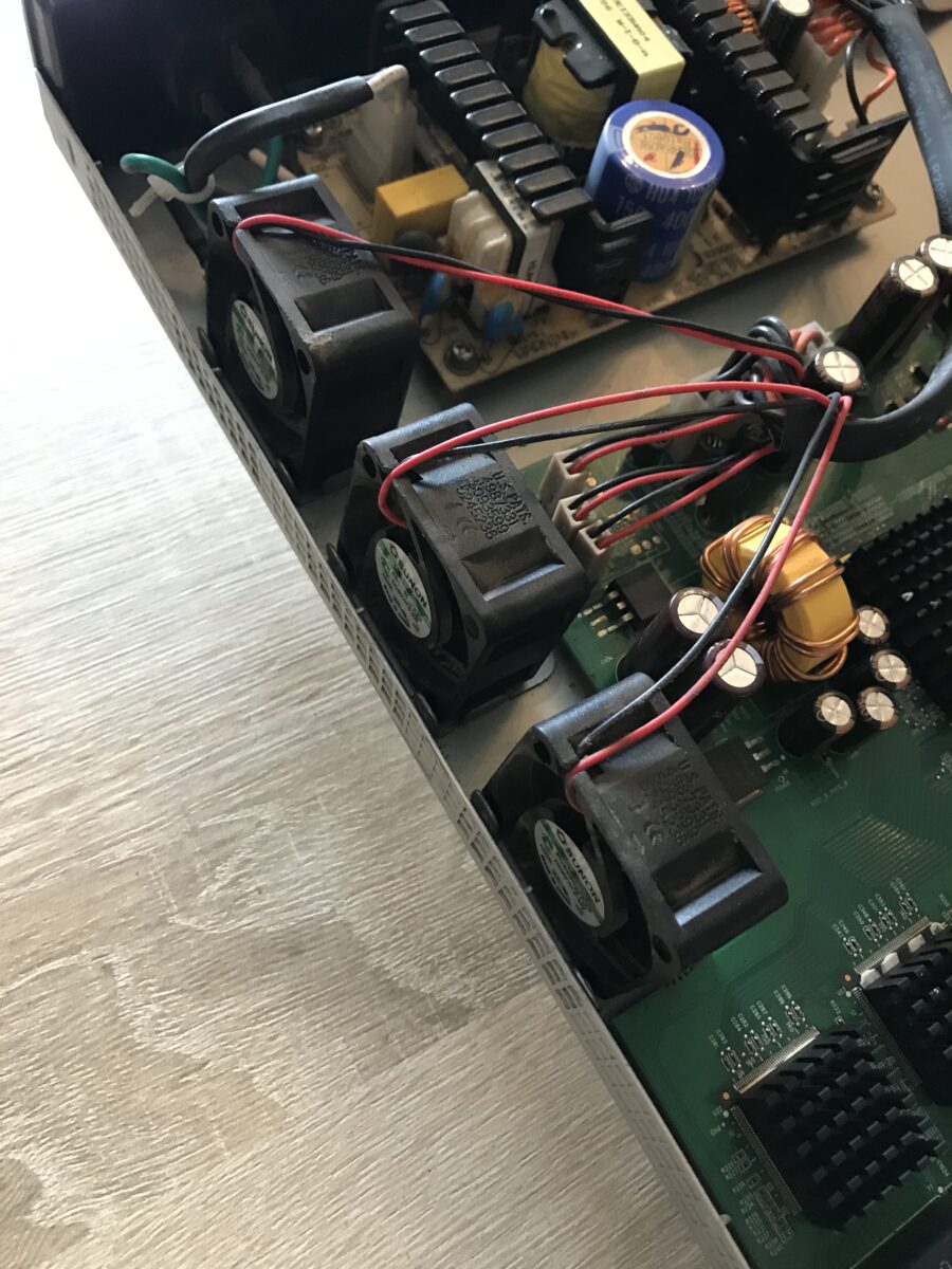
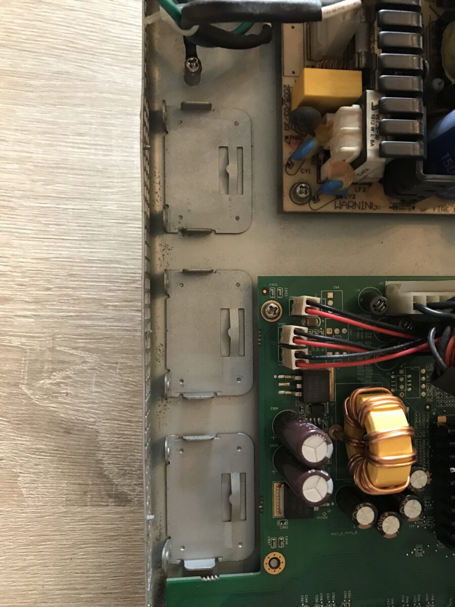
The fans are clamped into special brackets using bent metal: To remove them, it is advisable to use a flathead screwdriver to gently bend up the flat side of the construction (at the edge of the lower part of the housing) and remove the respective fan by tilting it sideways toward the circuit boards.
Unfortunately, all three of the bearings in the installed fans are defective and are not standard components: 40 x 40 mm size with a depth of 20 mm, 5 volts DC with 0.4 watts power consumption, not speed controlled. The OEM manufacturer is Sunon, but the specific model was too expensive for me because it is hardly available and officially only for commercial customers:
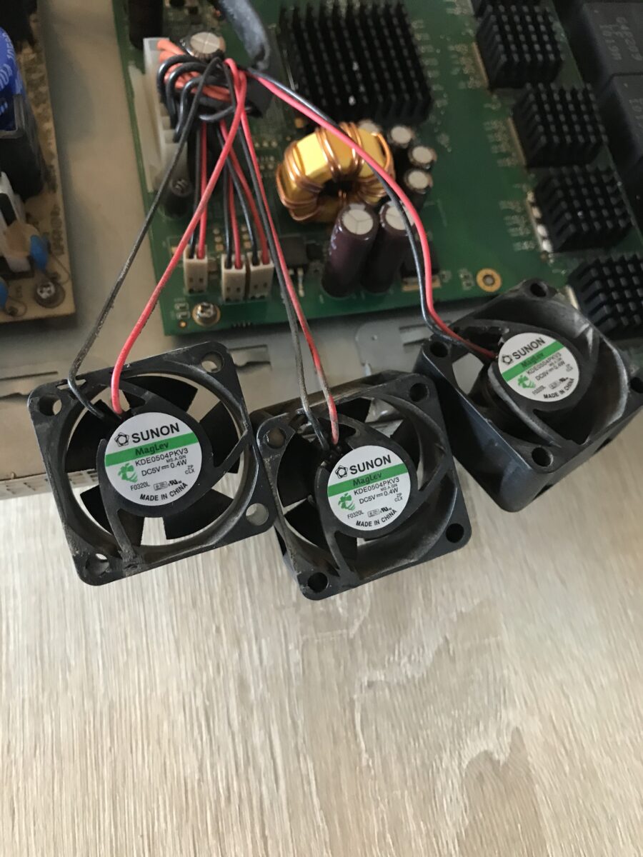
As an alternative to the built-in model “KDE0504PKV3”* I used the slightly quieter and significantly cheaper model “MF40200V3-1000U-A99”* also from Sunon. Other fans with these dimensions and specifications are available from Delta Electronics, for example, or from no-name suppliers (not a good idea, as a switch is a 24/7 device!). The replacement I used does not come with a plug, so I simply cut off the plugs from the original fans, soldered them to the new ones, and insulated them (heat shrink tubing*). Here is a comparison of the technical characteristics:
| Original | Replacement | |
|---|---|---|
| Manufacturer Model | Sunon KDE0504PKV3 | Sunon MF40200V3-1000U-A99 |
| Dimensions (W x H x D) | 40 x 40 x 20 mm | 40 x 40 x 20 mm |
| Operating voltage (Min. – Max.) | 5 Volts (4.0 V – 5.5 V) | 5 Volts (3.5 V – 6 V) |
| Current | 0.080 Ampere | 0.087 Ampere |
| Power | 0.40 Watts | 0.44 Watts |
| Air flow rate | 6.30 m³/h | 10.71 m³/h |
| Rotational speed | 5200 rpm | 5000 rpm |
| Maximum volume | 18.0 dB | 16.5 dB |
| Bearing | Vapo (magnetic) | Vapo (magnetic) |
| Lifetime | 40.000 h | 60.000 h |
Remove and clean the motherboard
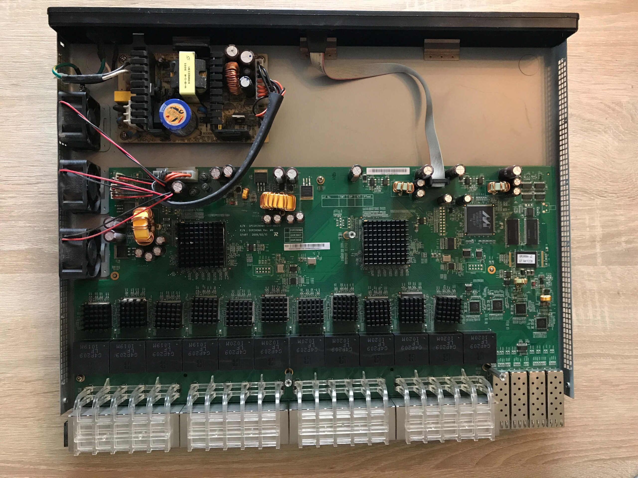
To remove the motherboard, the ribbon cable for console access and the power supply connector (caution: potential residual voltage!) must be removed. Then the three spacers and the remaining PH2 screws must be unscrewed. Now you can remove the circuit board from the lower part of the housing. Here, all components have already been cleaned and are ready for reassembly:
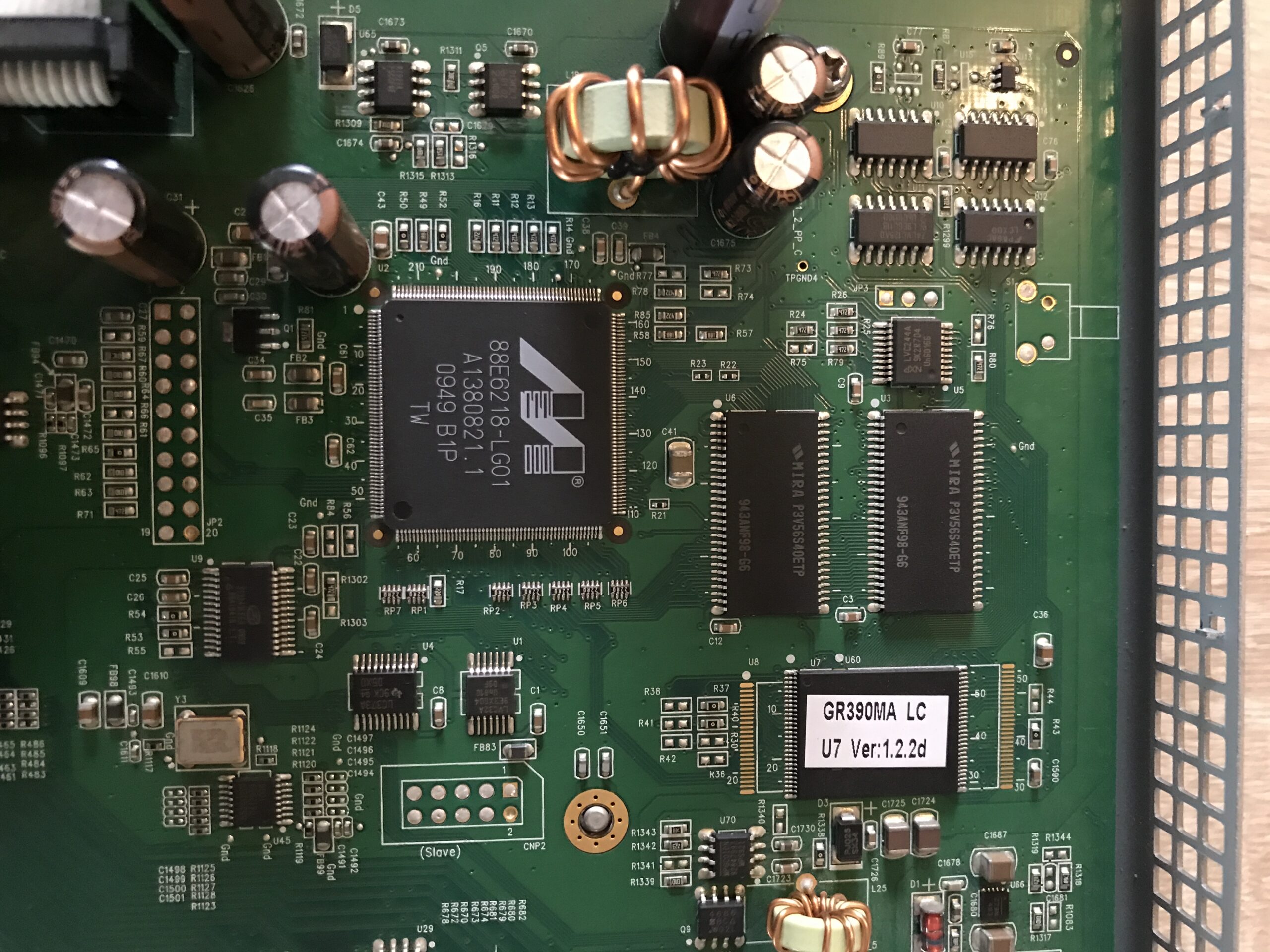
The sticker on the flash chip suggests that this unit was already shipped with the latest firmware version (v1.2.2d) and therefore no update will be necessary.
Configuration?
I connected the SRW2048 via a power cable* to power and to our home network via a network cable* connected to port 1. After several attempts, the switch was not assigned an IP address. I suspected that the integrated HTTP/HTTPS server, which should provide the WebView configuration, was disabled.
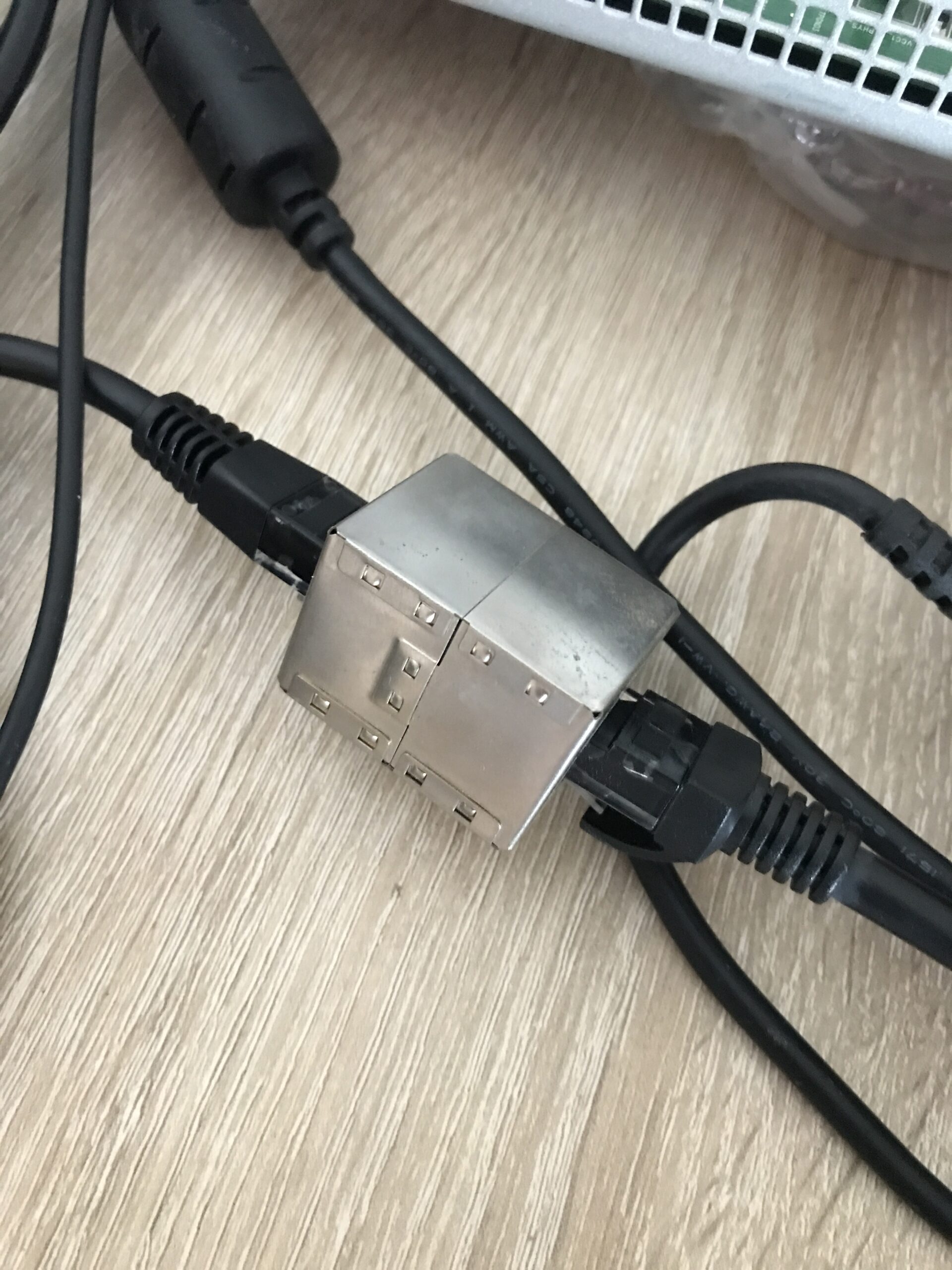
This leaves access via the serial console port on the rear panel. This is where the next problem arises: I don’t have the double female DB9 cable (null modem*) that was originally supplied. However, I do have several console cables for newer Cisco switches, which are designed as female DB9 serial to RJ-45. Using an RJ-45 coupler*, I then put together a double female cable:
Next, you need a computer with a serial port (or a serial-to-USB adapter, which I don’t have). The docking stations for the HP EliteBook 8540p have one, so I used mine and installed PuTTY and Tftpd64 (for a possible firmware update that doesn’t exist) on it.
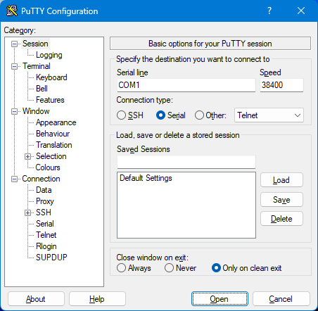
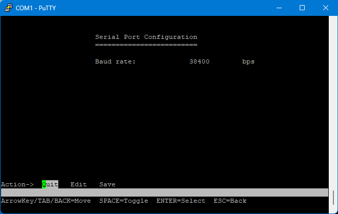
The correct settings are:
| Property | Value |
|---|---|
| Speed | 38400 |
| Data bits | 8 |
| Stop bits | 1 |
| Parity | None |
| Flow Control | None |
Here is a screenshot of PuTTY (only the correct speed needs to be entered):
The initial contact
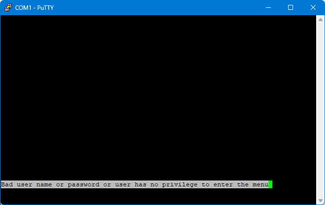
If the switch is already running and you only establish the connection then, you will initially only see an empty terminal. However, after pressing “Return” you will see that everything is correct and a response will appear:
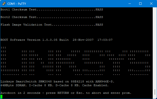
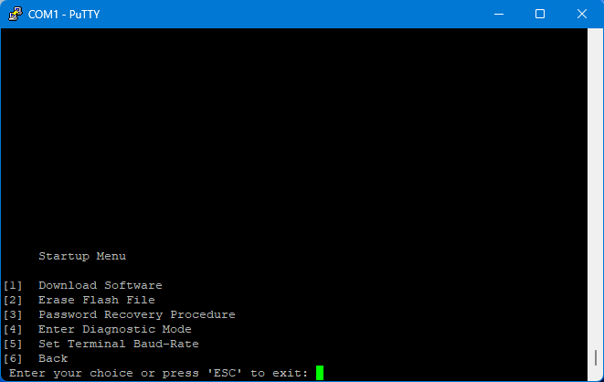
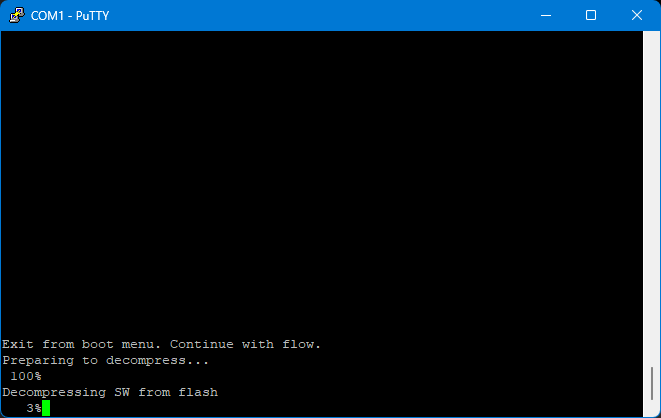
To access the boot menu and configuration, leave the serial connection as it is and power cycle the switch, i.e., briefly disconnect and reconnect the power. After all LEDs light up briefly as with every boot, you can now watch the firmware POST live and interrupt it with “ESC” to enter the boot menu. This is particularly important if you do not know the access data and want to reset it, or if you are trying to solve other problems:
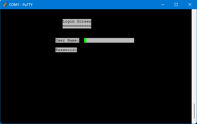
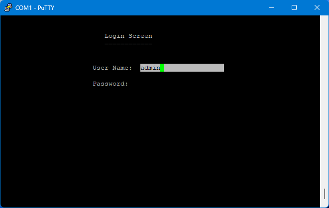
Once the boot process is complete, you will be greeted with this login screen. By default, the username is “admin” and the password is either blank or also “admin” . In my case, I was able to log in with a blank password field:
Finally, access!
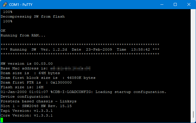
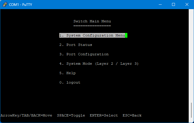
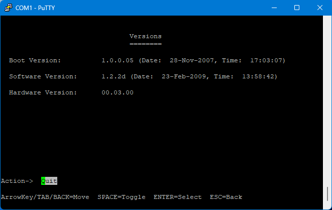
For documentation purposes, I took lots of screenshots of everything, divided into menu categories. Maybe these will help someone in the future figure out what works and what doesn’t. As mentioned before, the latest firmware version v1.2.2d is installed.
System Configuration Menu
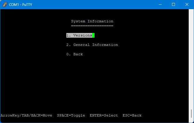
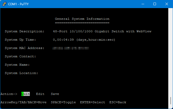
System Information
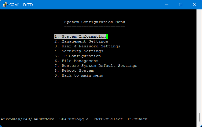
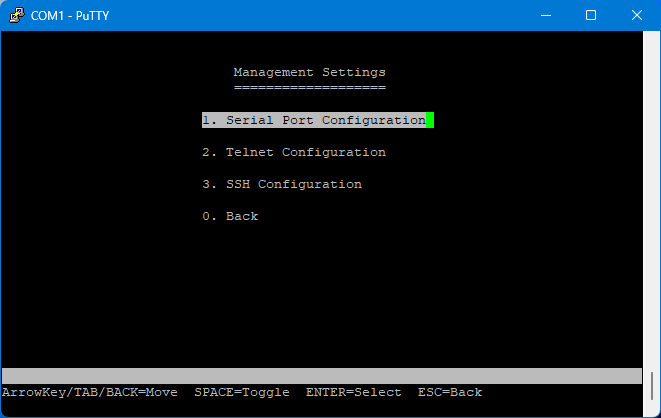
Management Settings
User & Password Settings

This is what it looks like with the default settings.
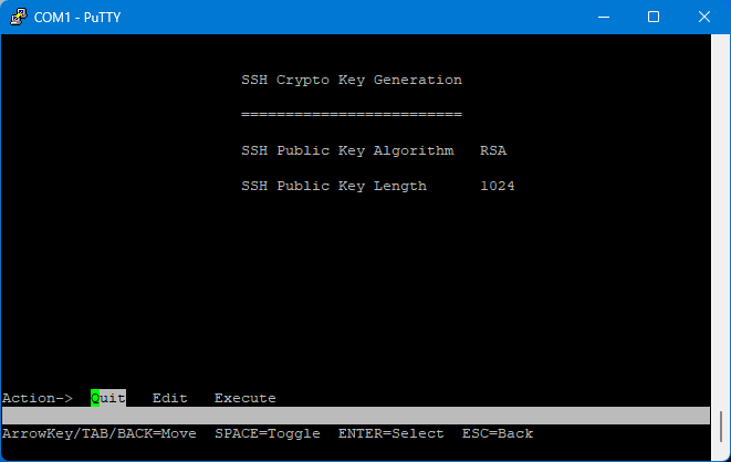
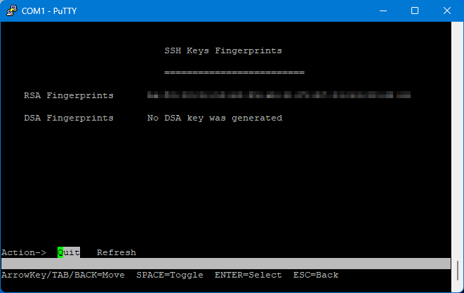
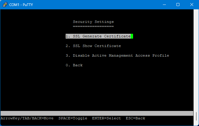
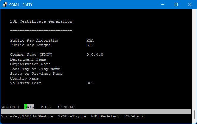
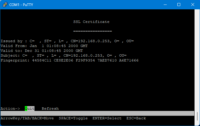
Security Settings
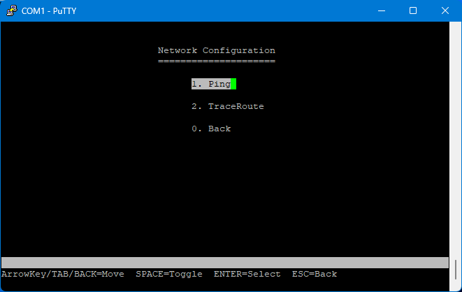
IP Configuration
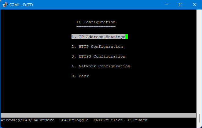
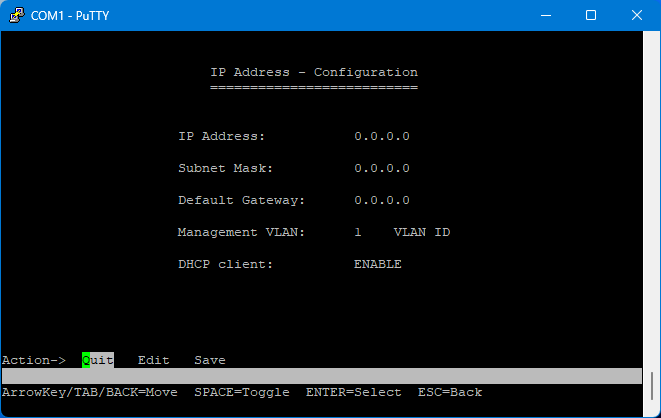
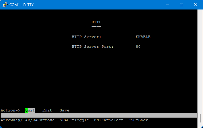
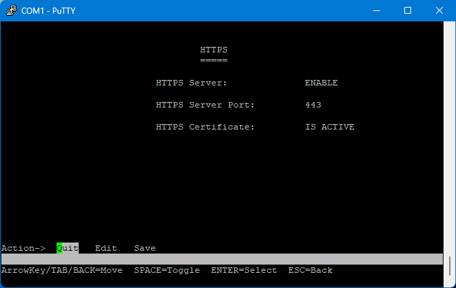
Here, “DHCP client” and “HTTP” and/or “HTTPS” must be set to “ENABLE” otherwise no IP address will be assigned for WebView or it will not be available!
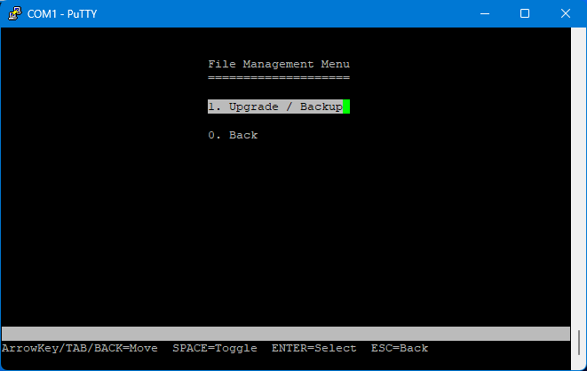
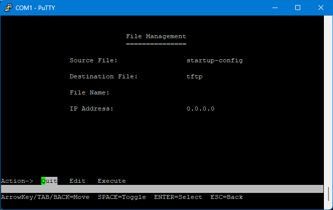
File Management
Port Status
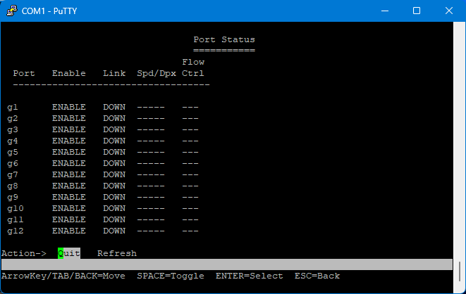
You can use the arrow keys to cycle through all available ports.
Port Configuration
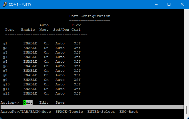
Here, too, you can navigate using the arrow keys.
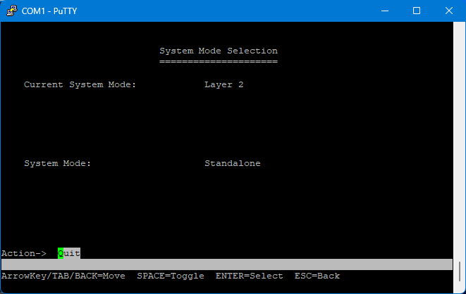
System Mode
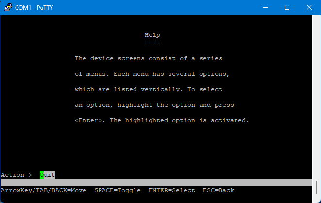
Help
Configuration options via WebView
After configuring everything as desired, I restarted the system using the menu option. And lo and behold: the switch now receives an IP address from the router in the network as configured and can also be accessed on this address. However, nothing works in the latest version of Firefox on Windows 11 and the view is very unusable, but in general, “WebView” should now work.
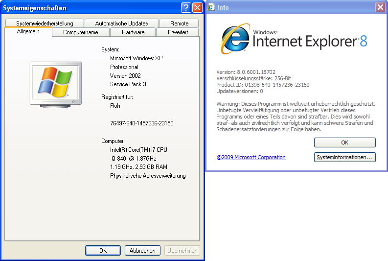
So I booted up the EliteBook with Windows XP and everything works as it should in Internet Explorer 8:
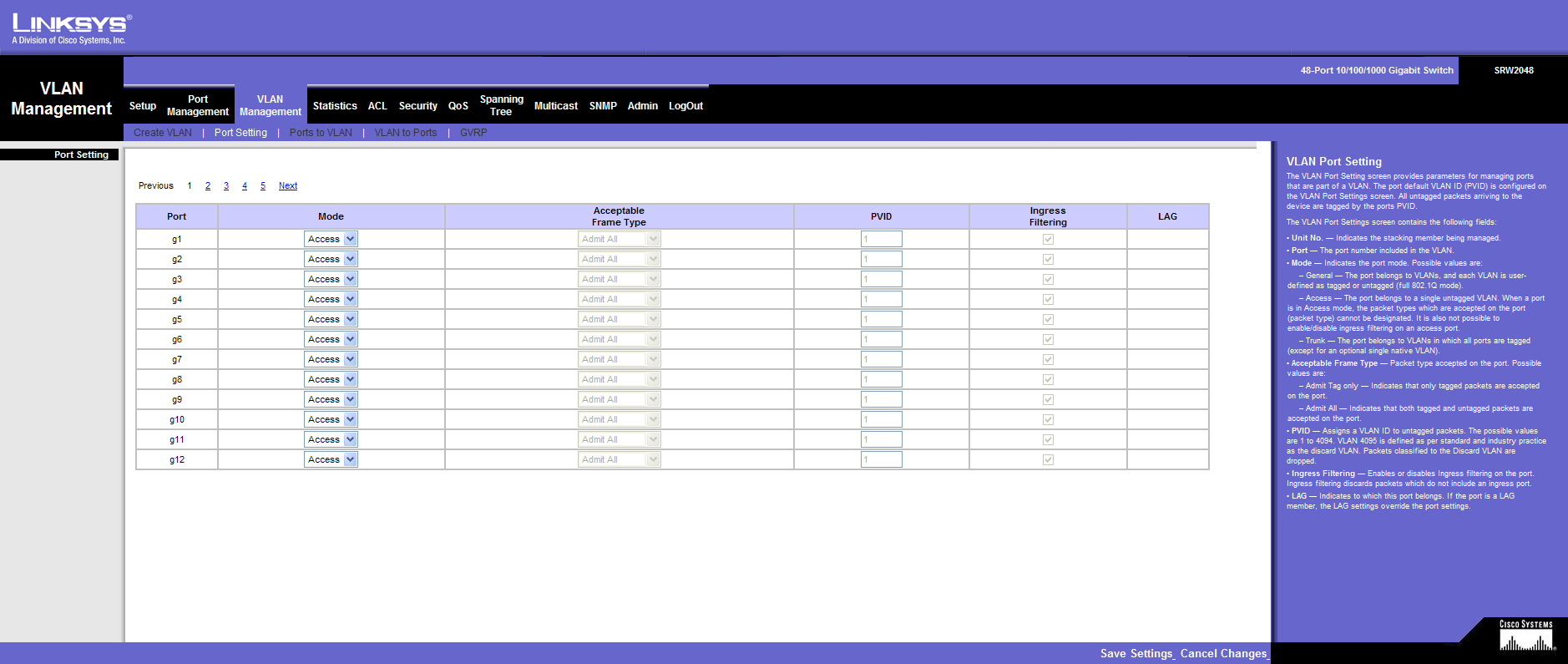
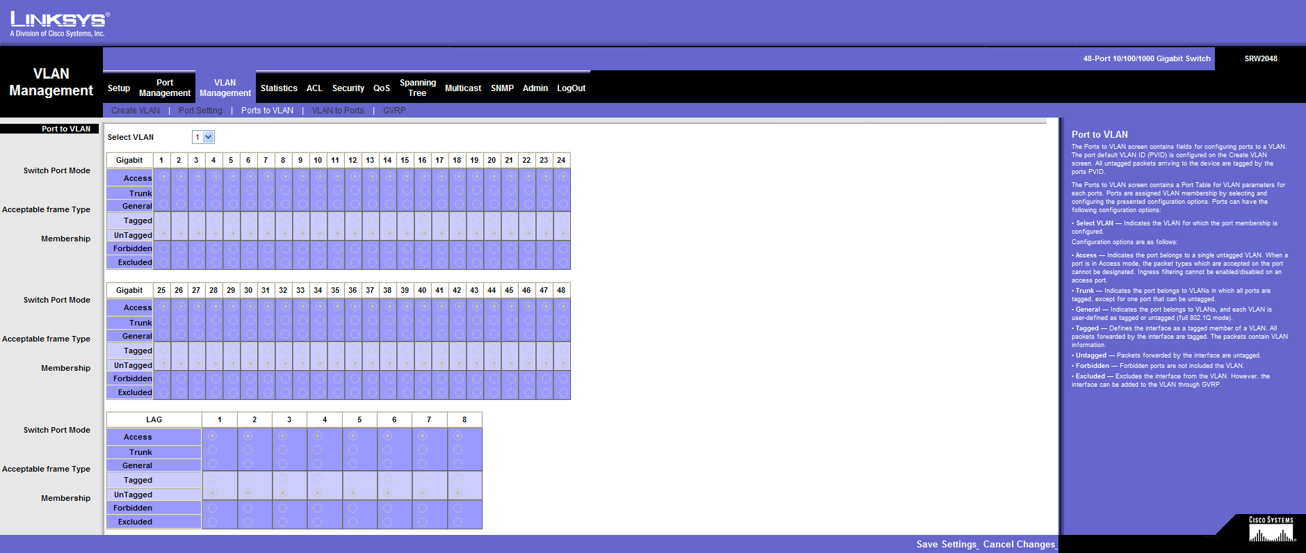
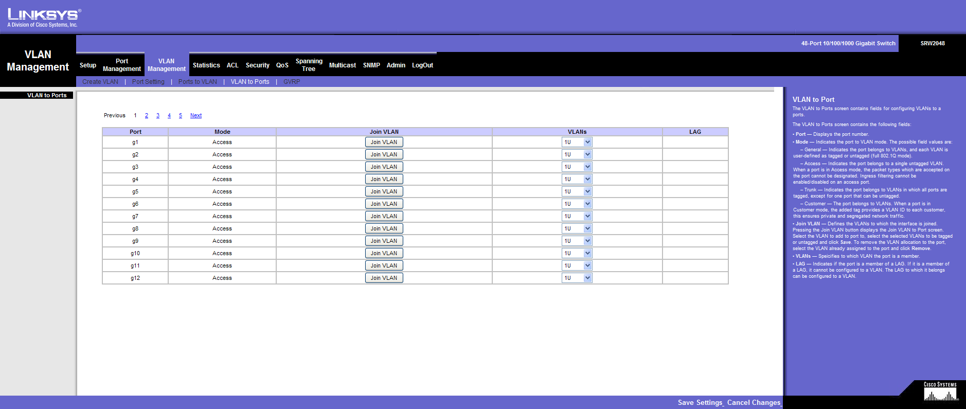
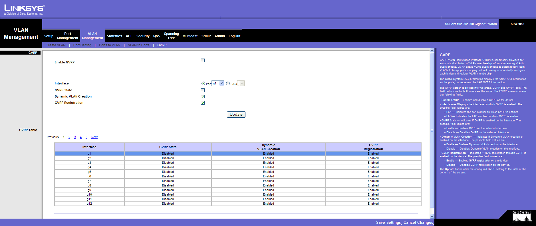
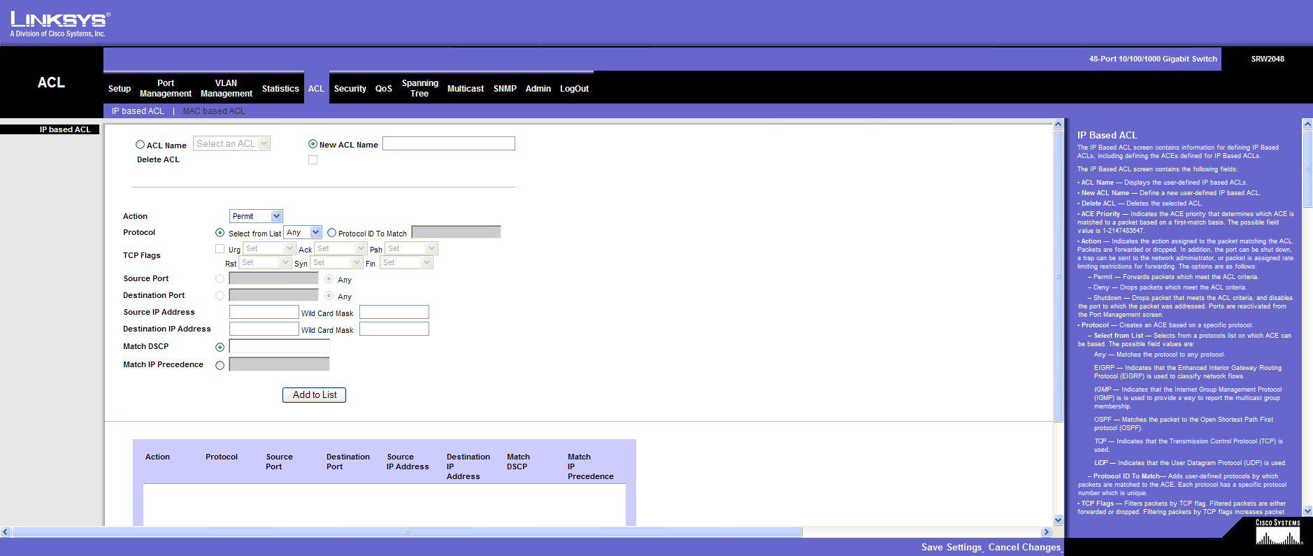
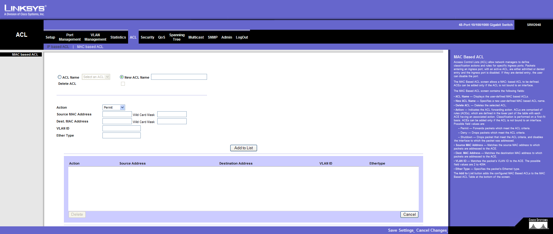
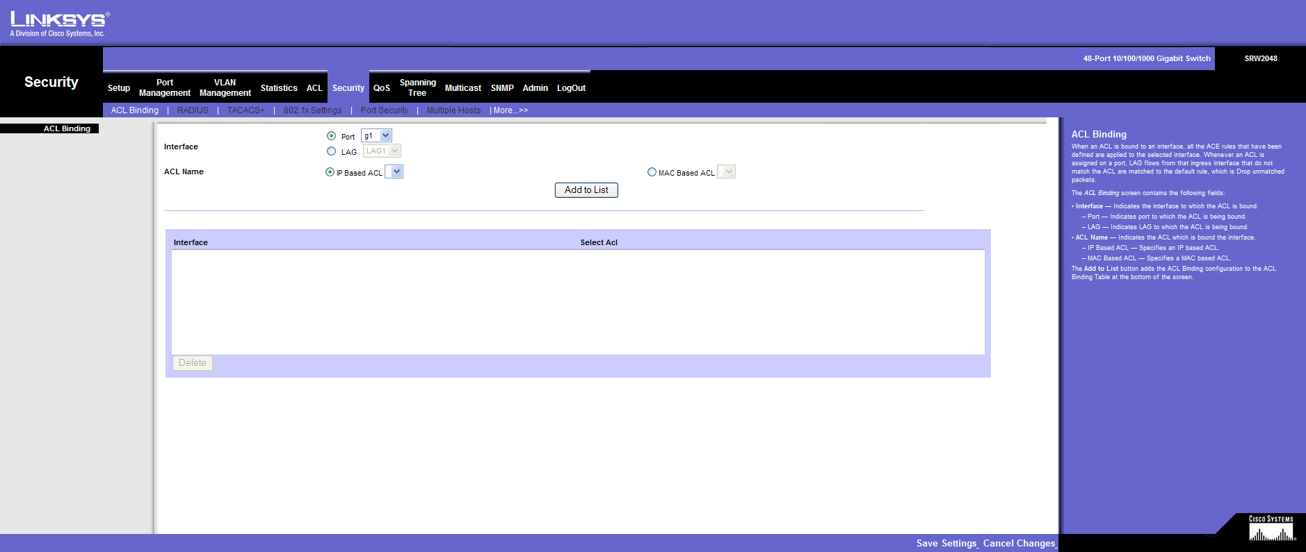
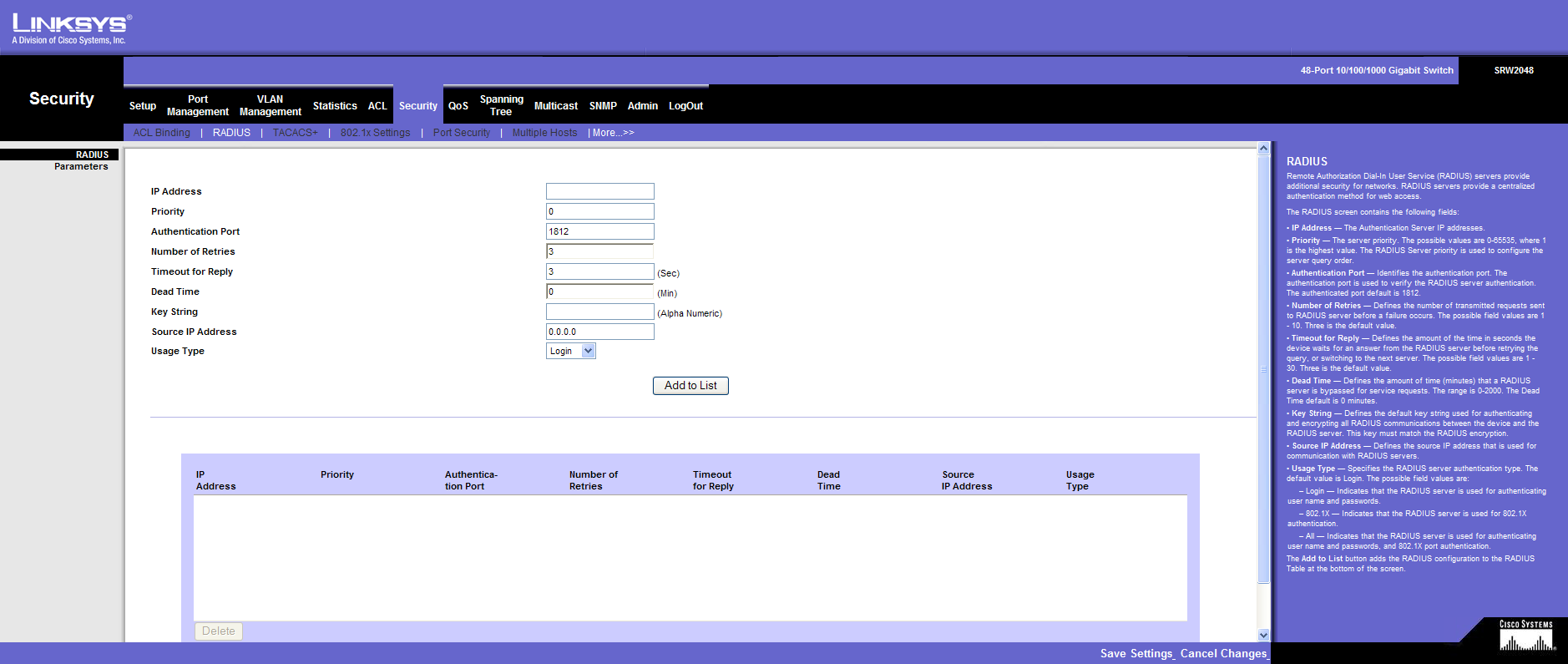
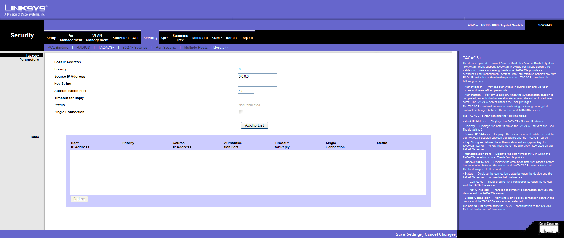
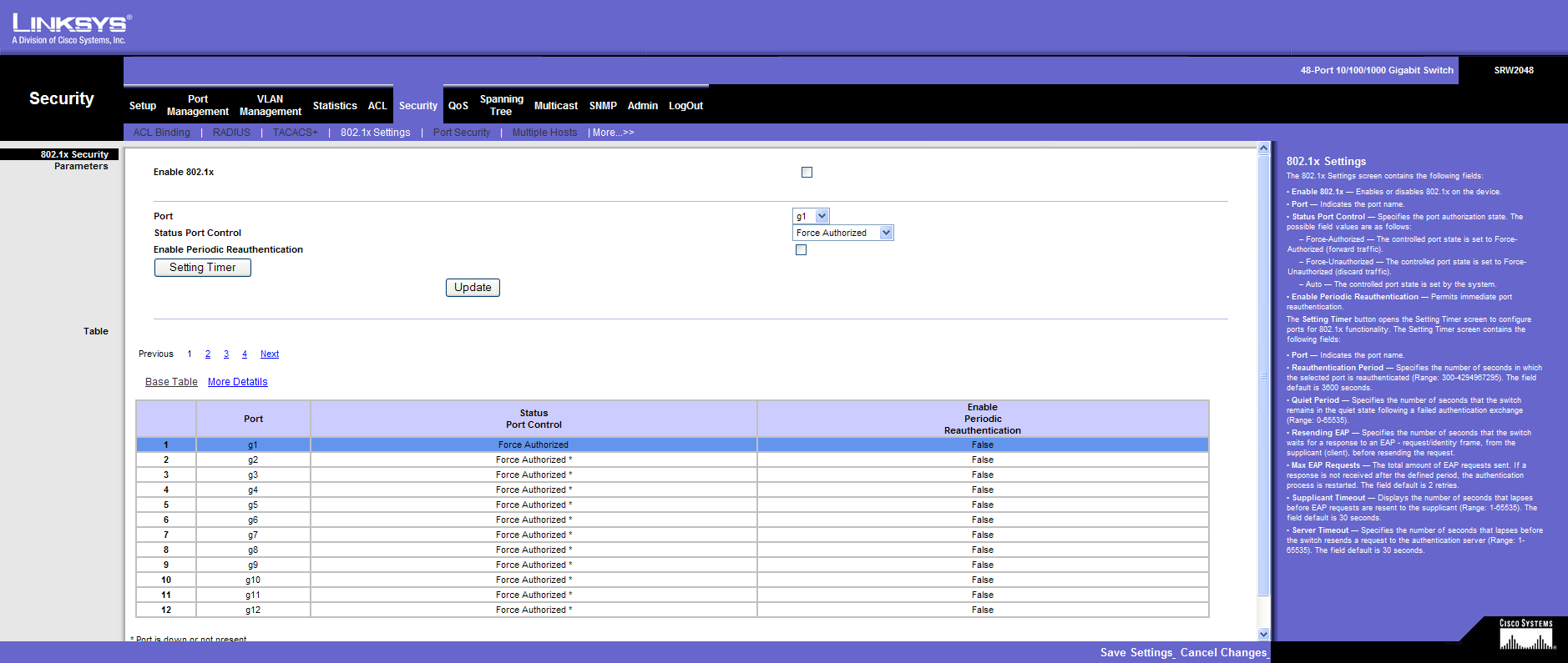
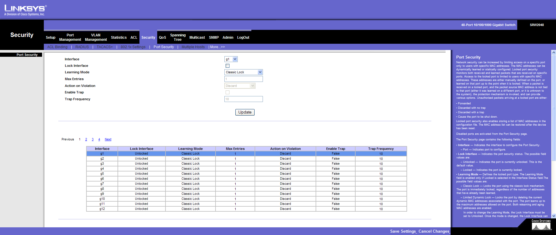
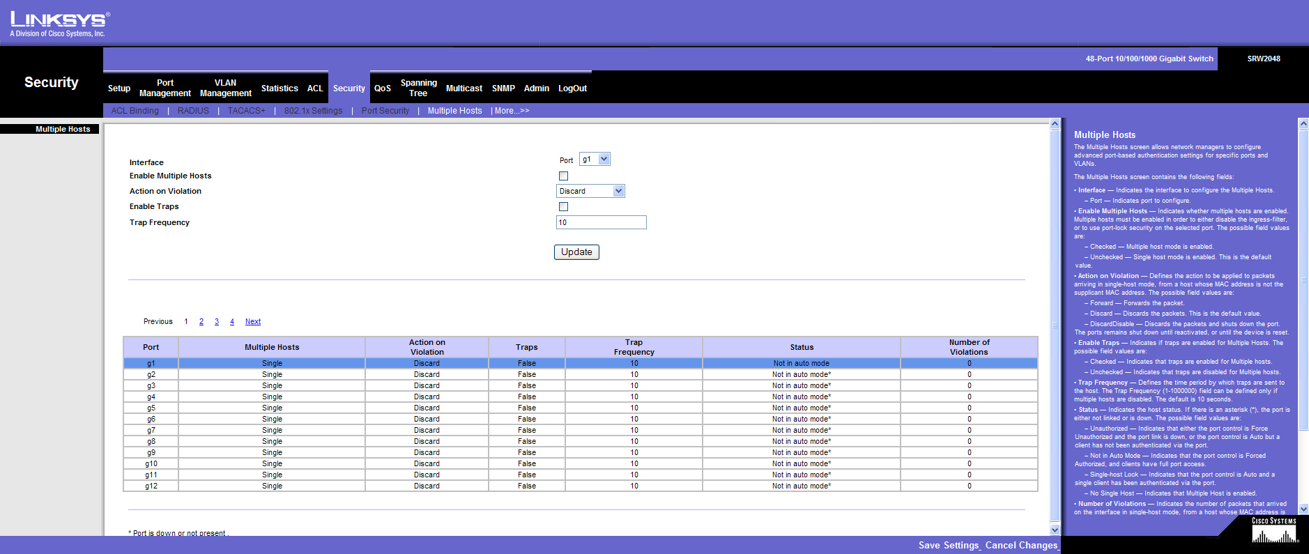
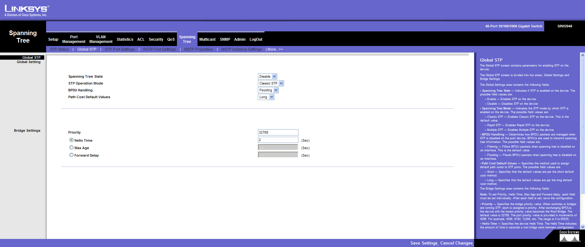
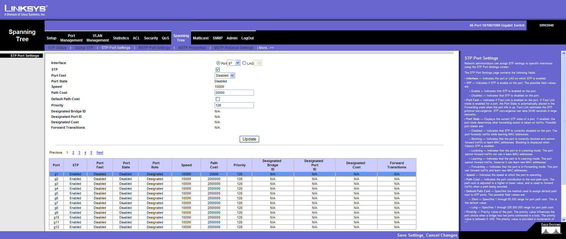
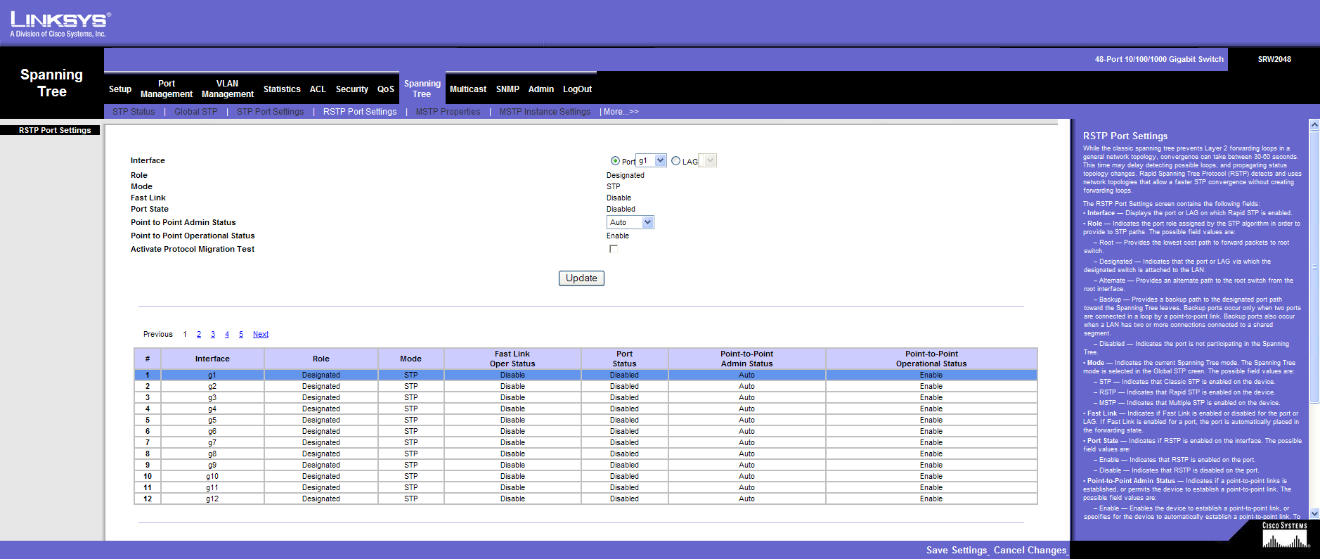
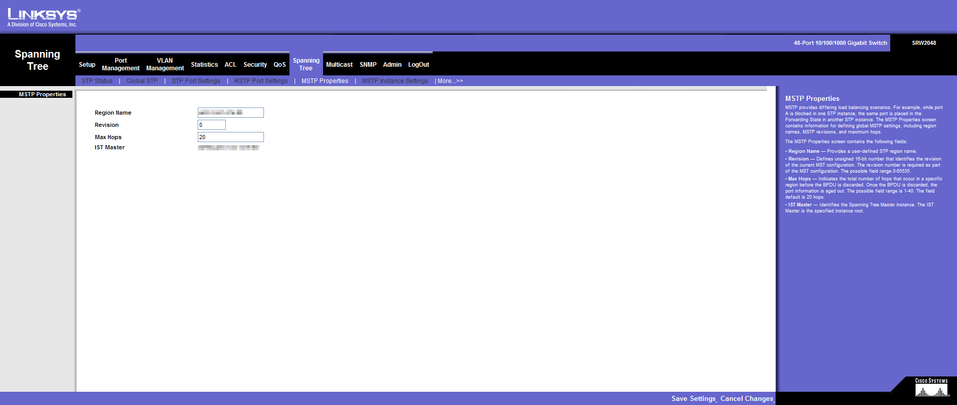
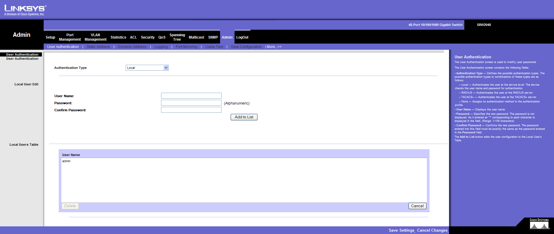
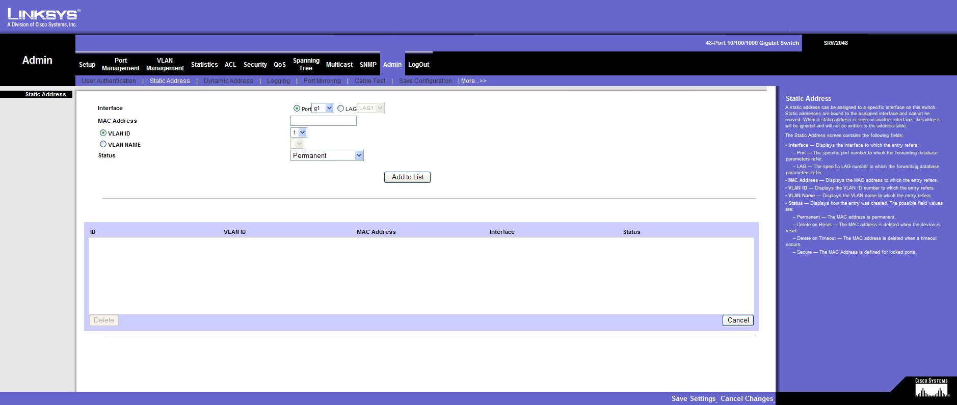
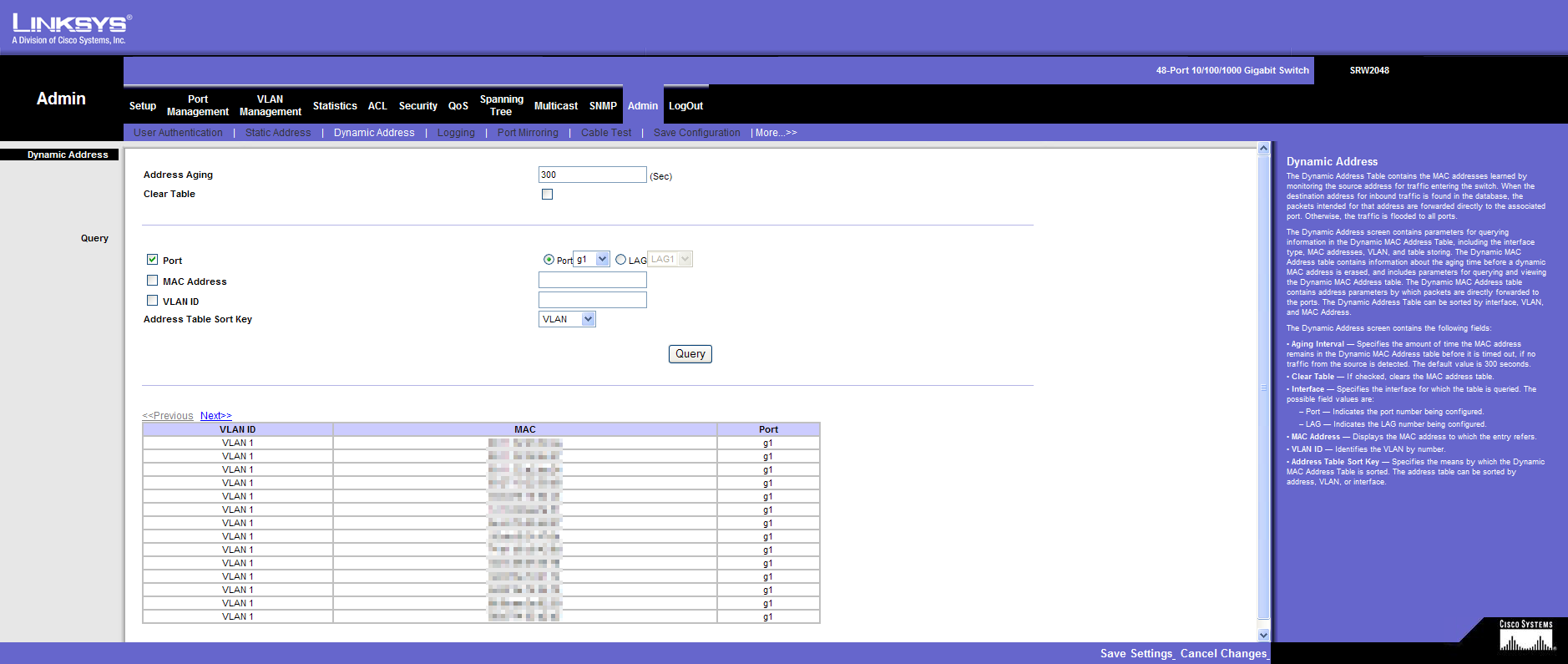
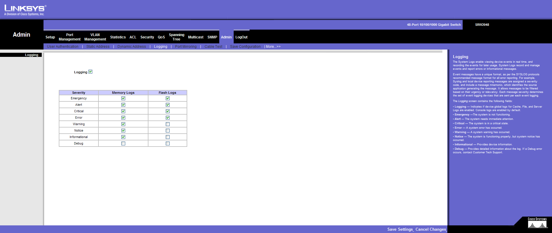
I have also documented the possibilities of WebView below:
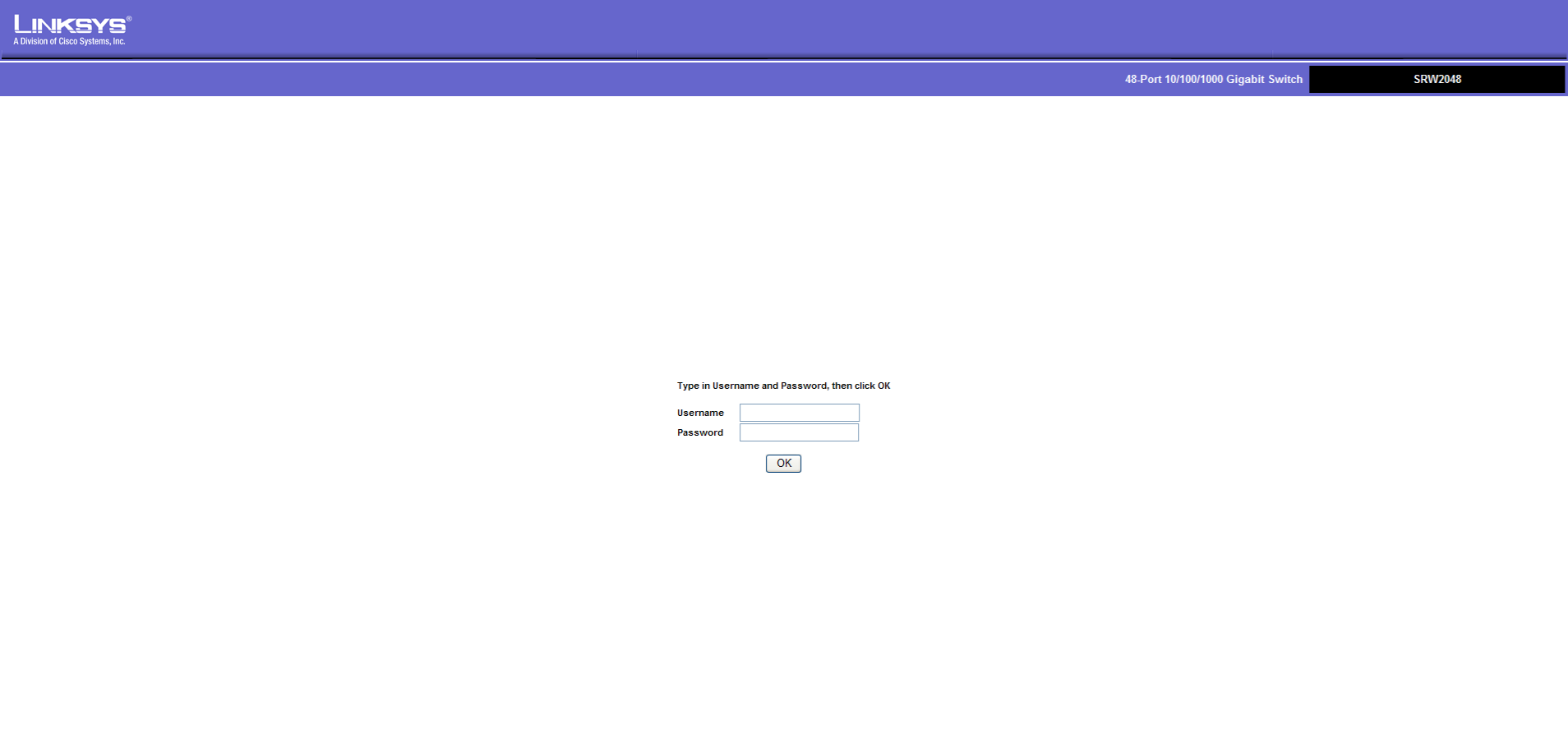
Login

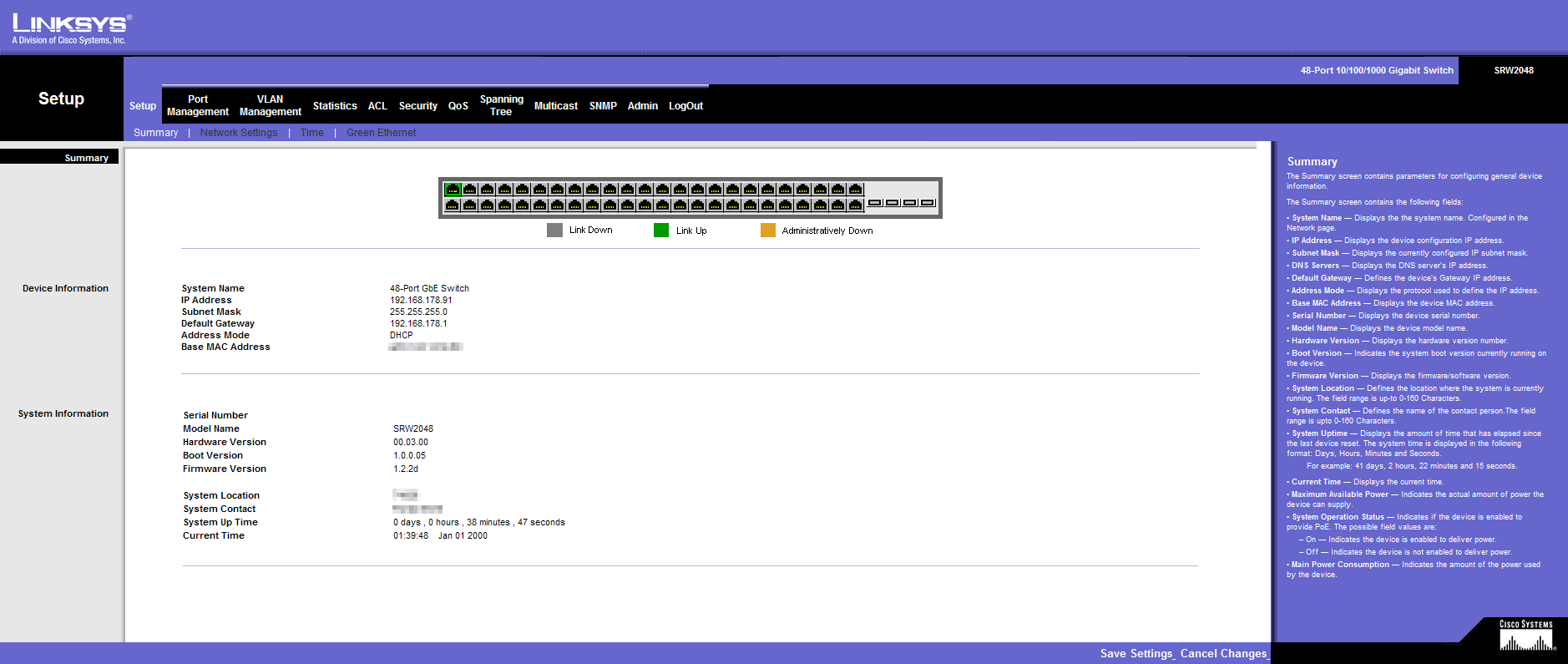
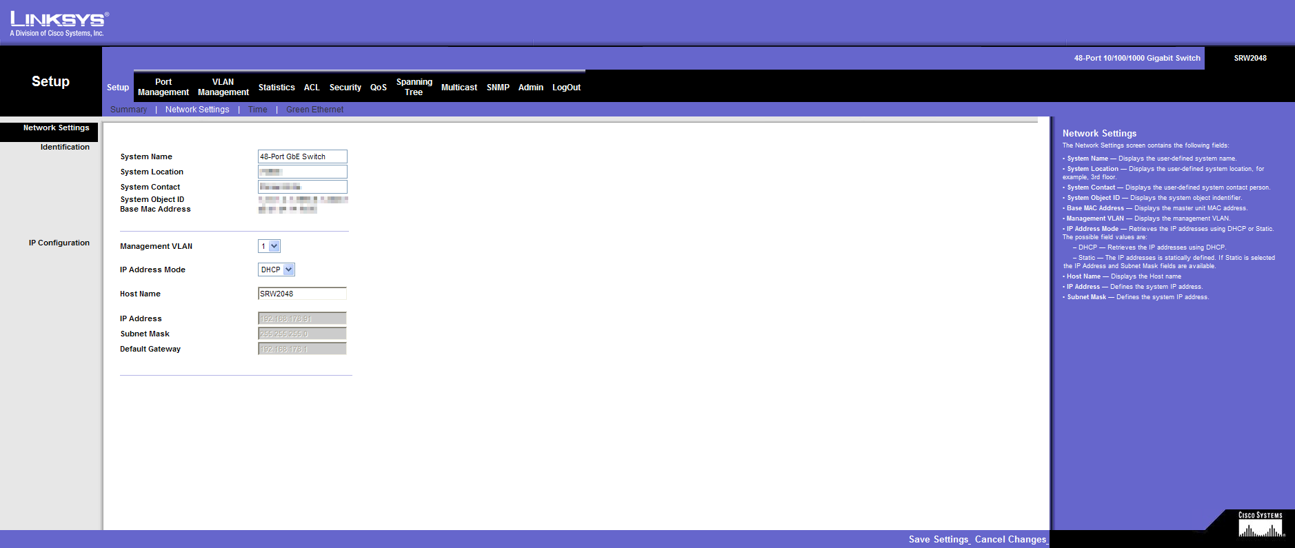
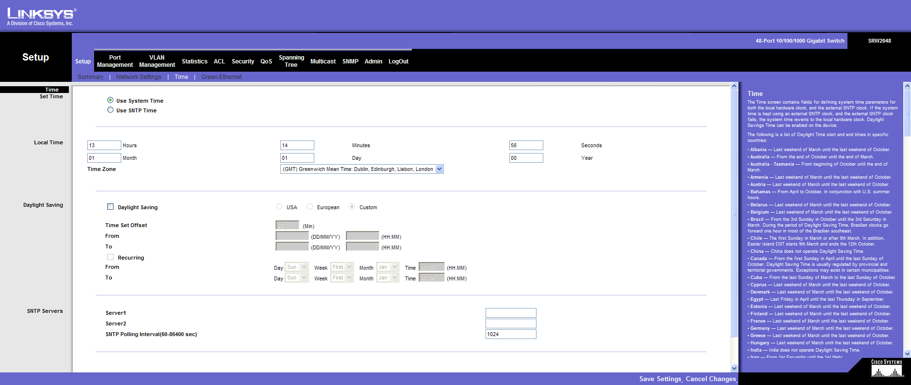
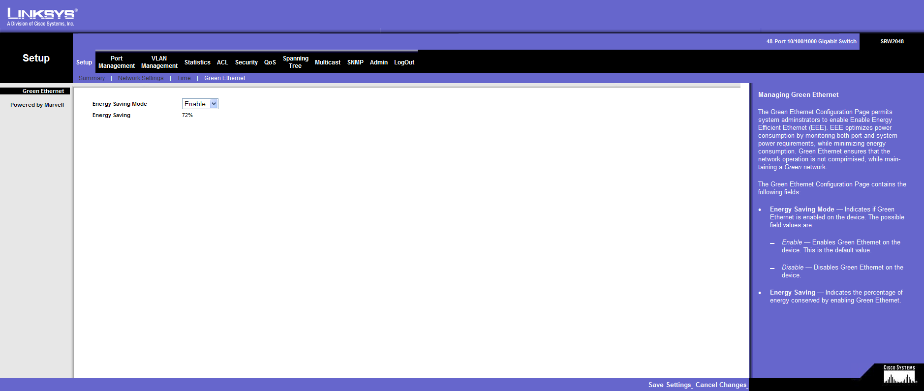
Setup
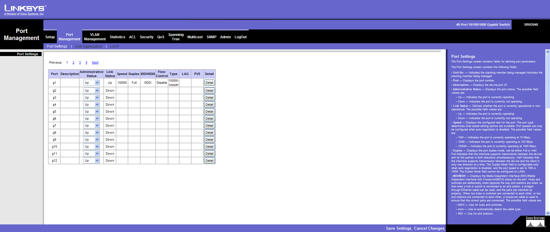
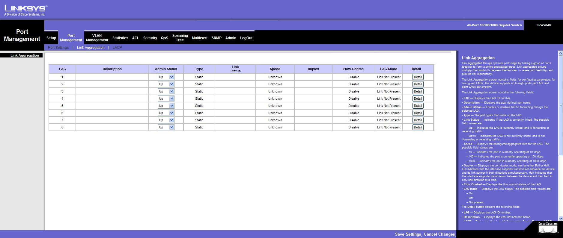
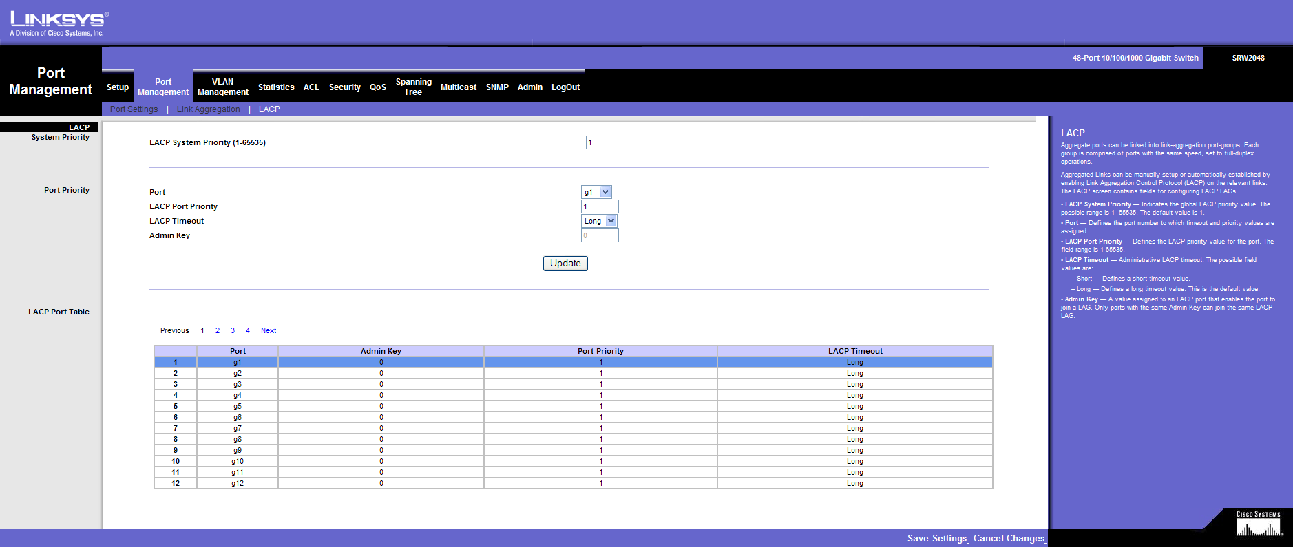
Port Management
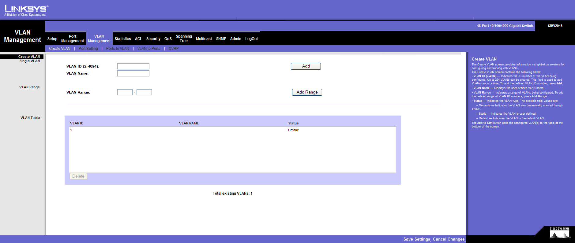
VLAN Management
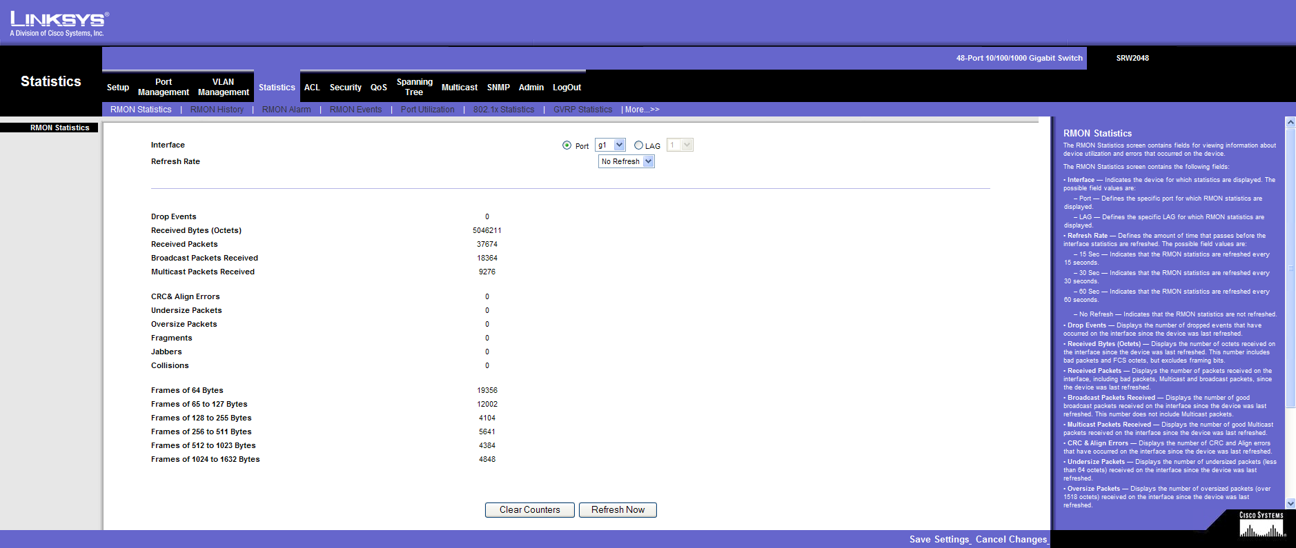
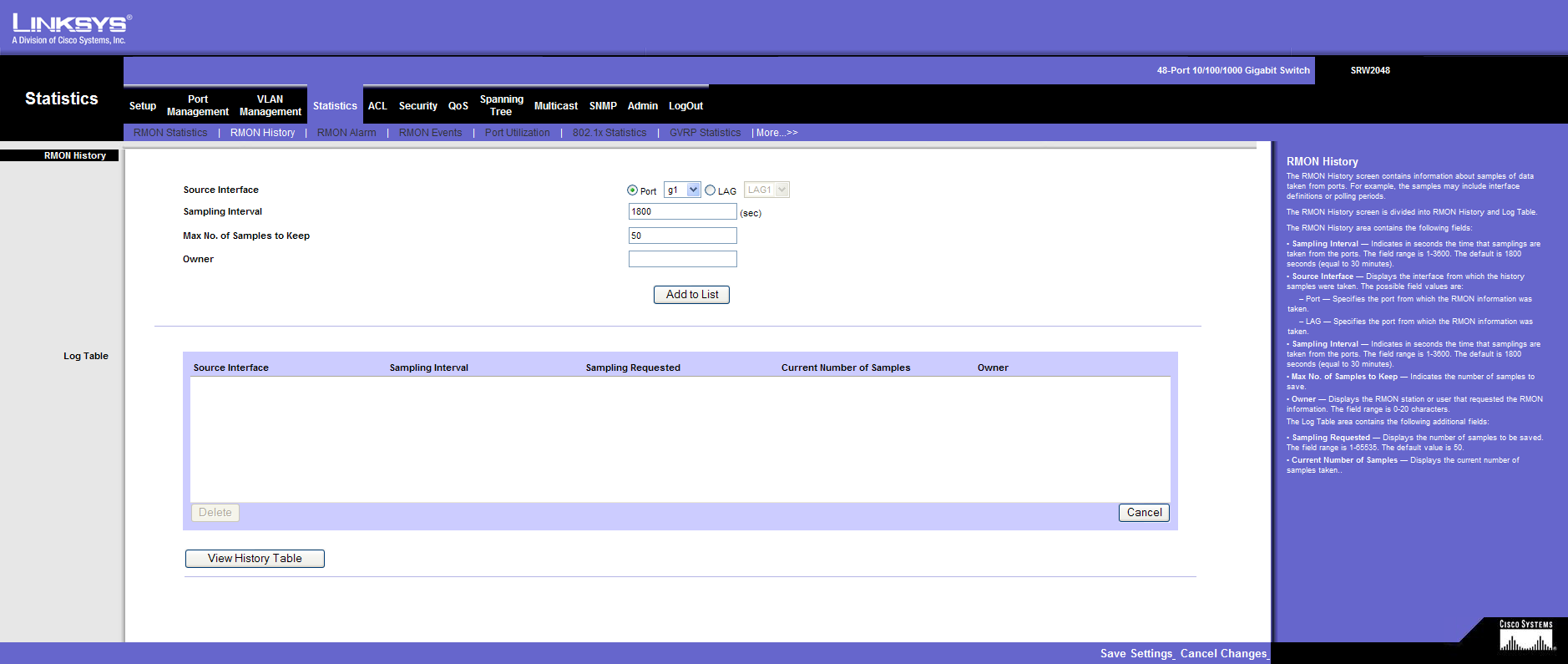
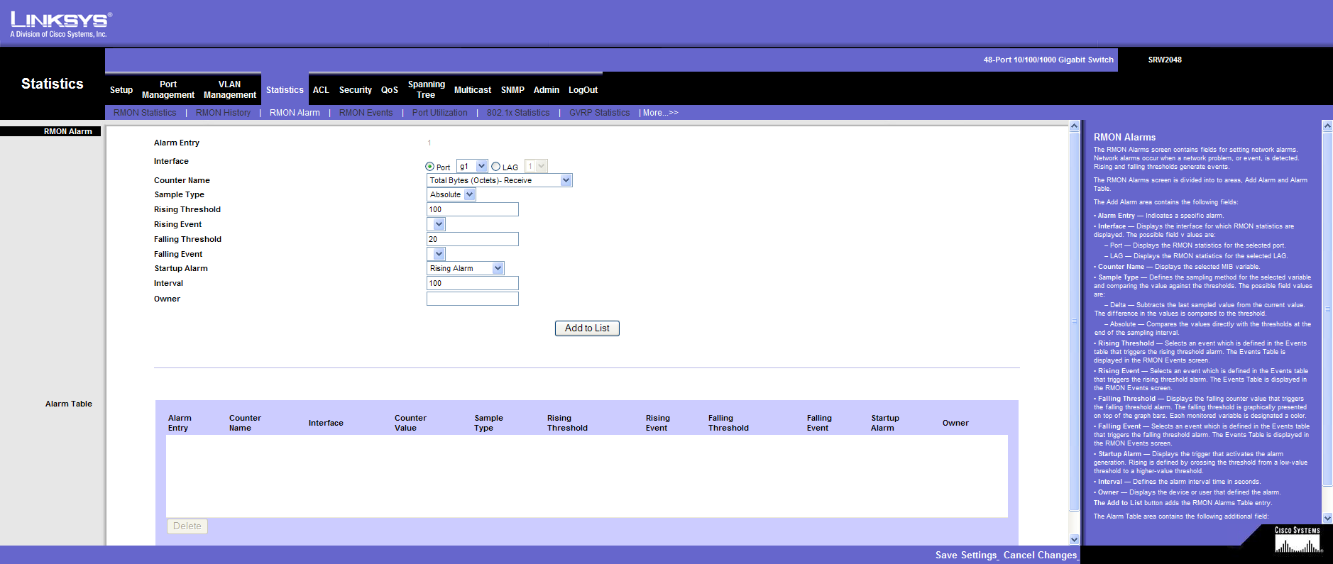
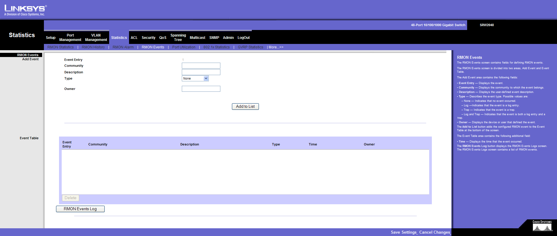
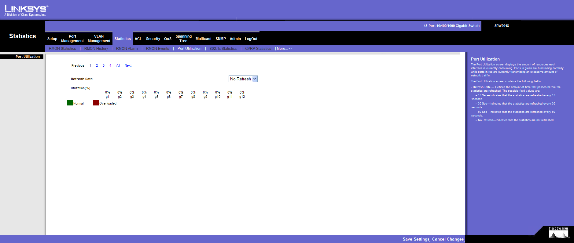
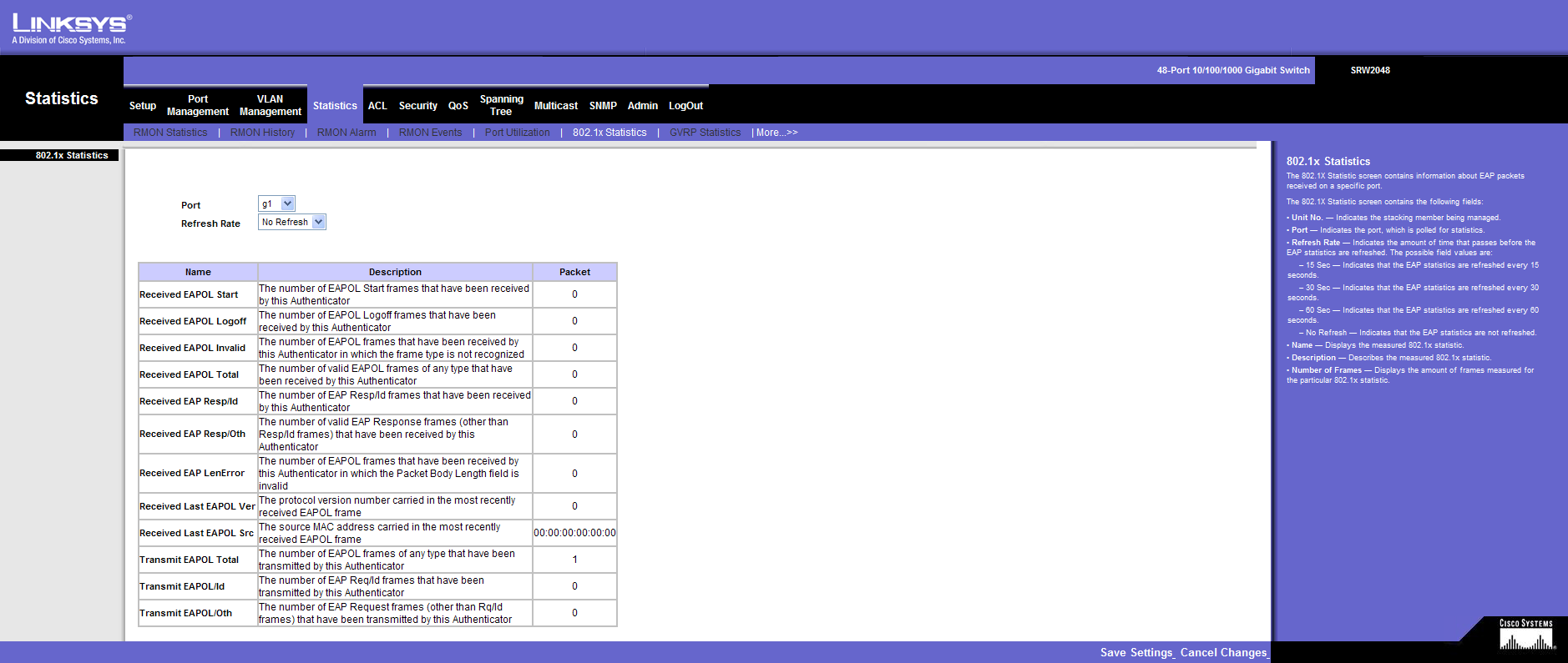
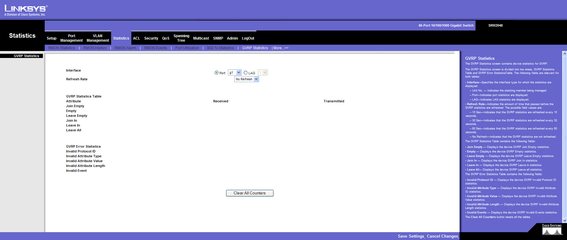
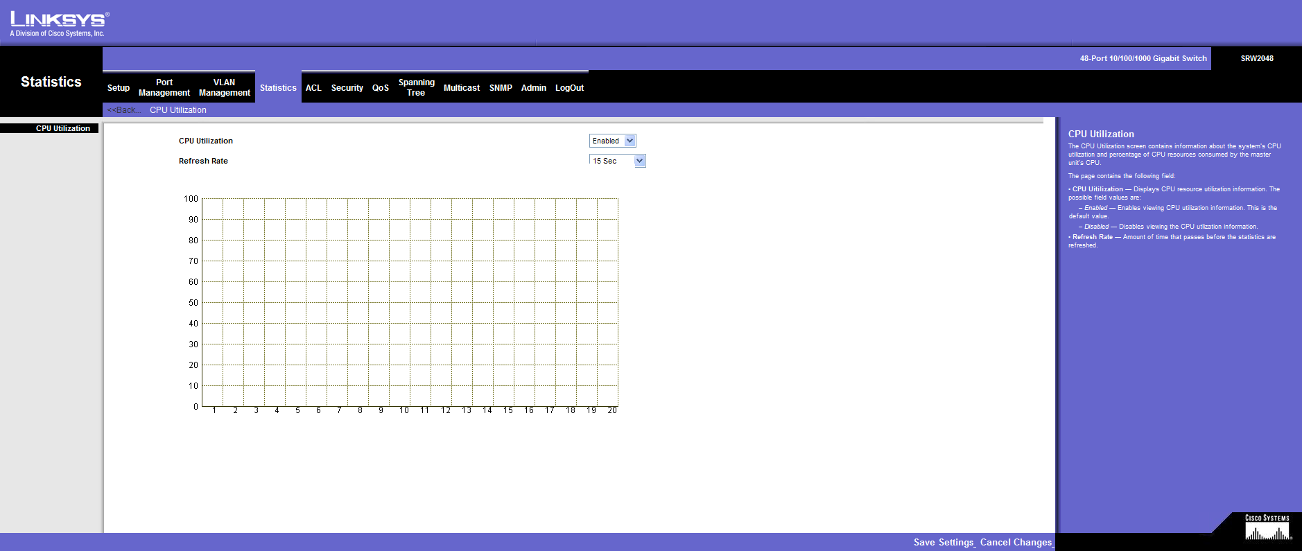
Statistics
ACL
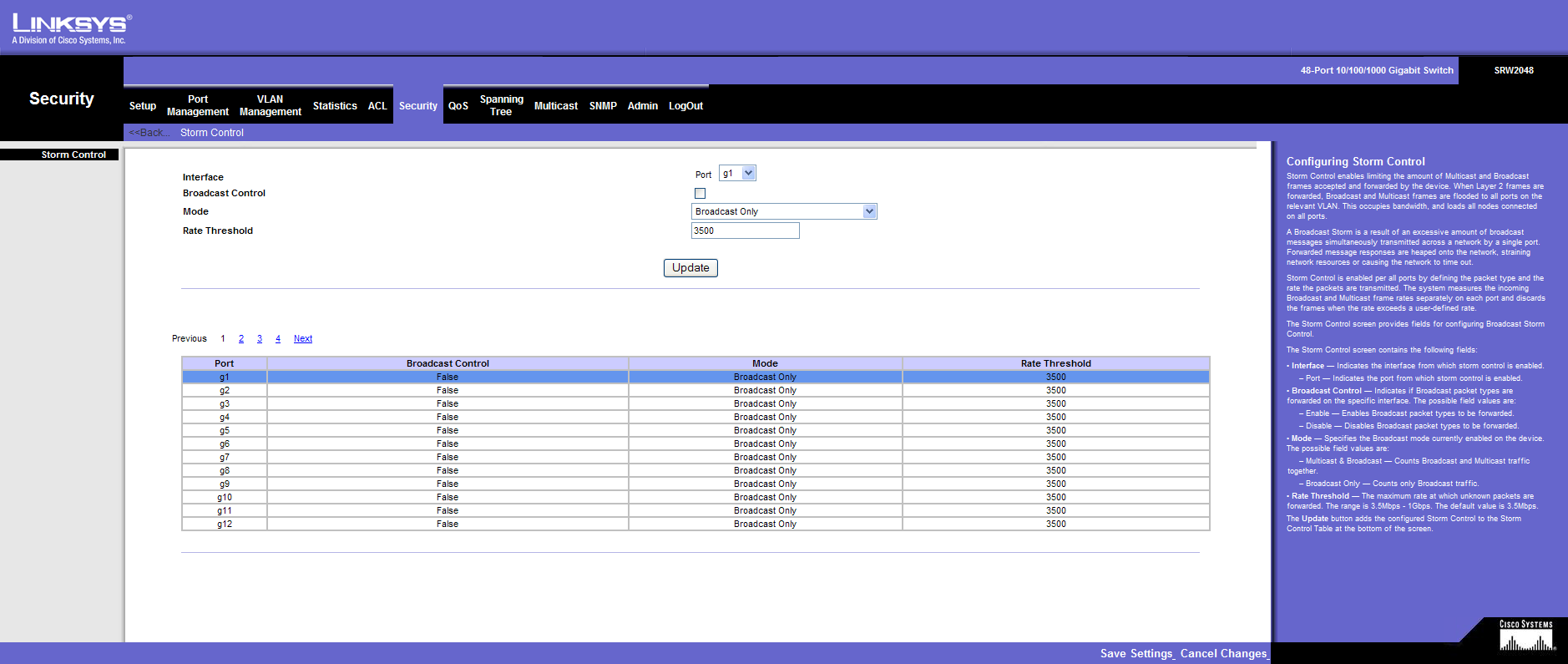
Security
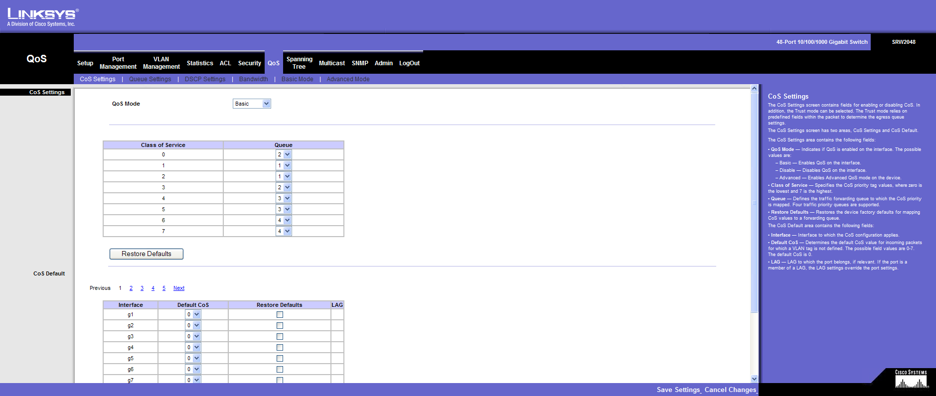
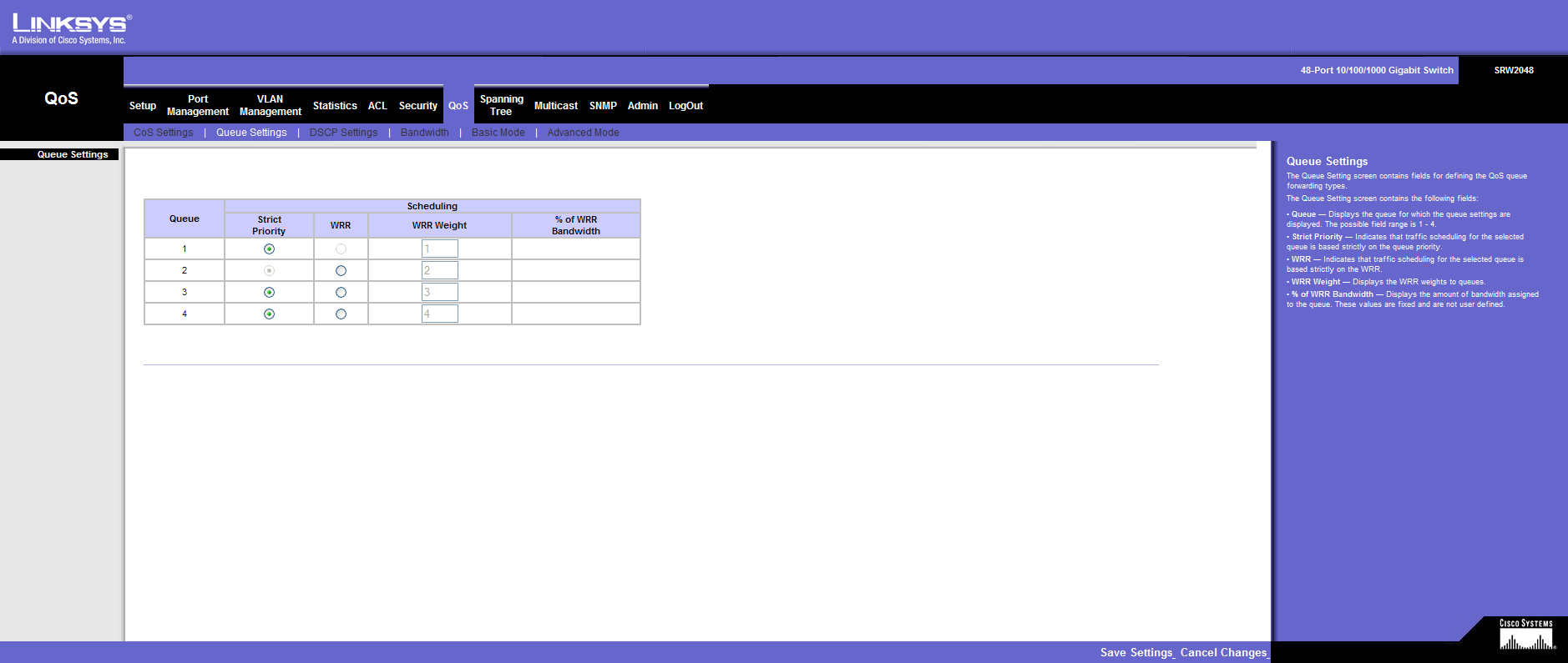
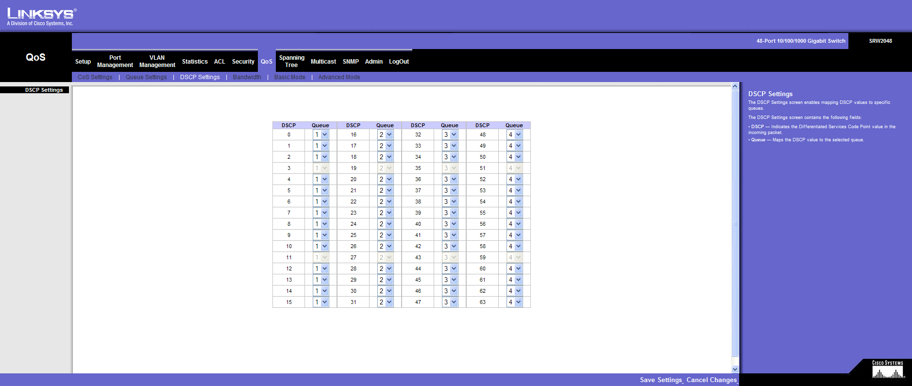
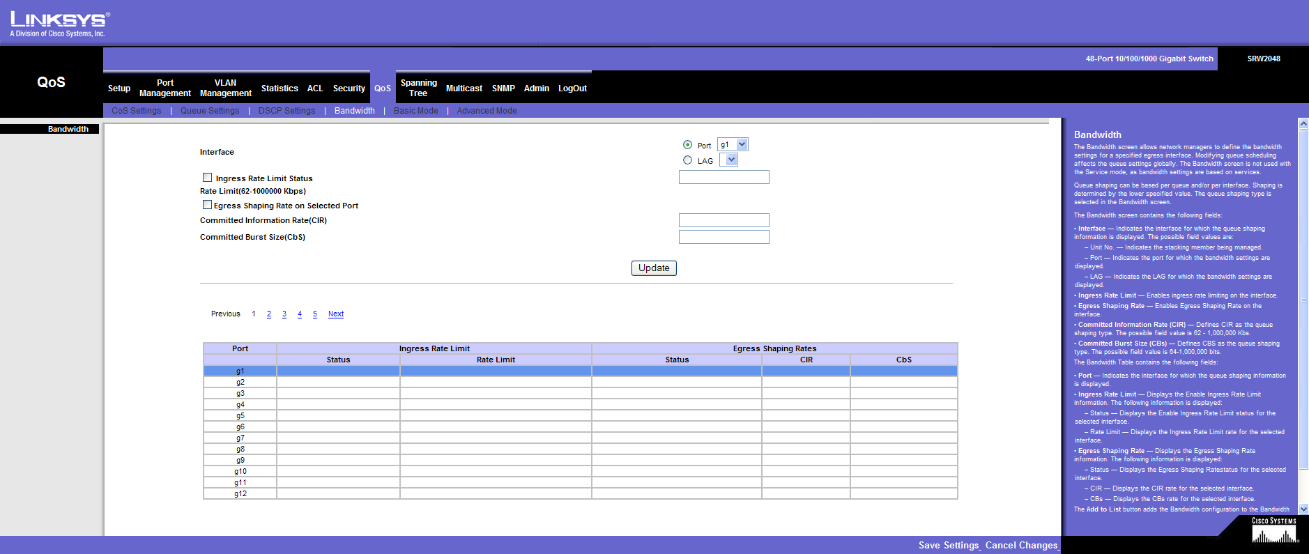
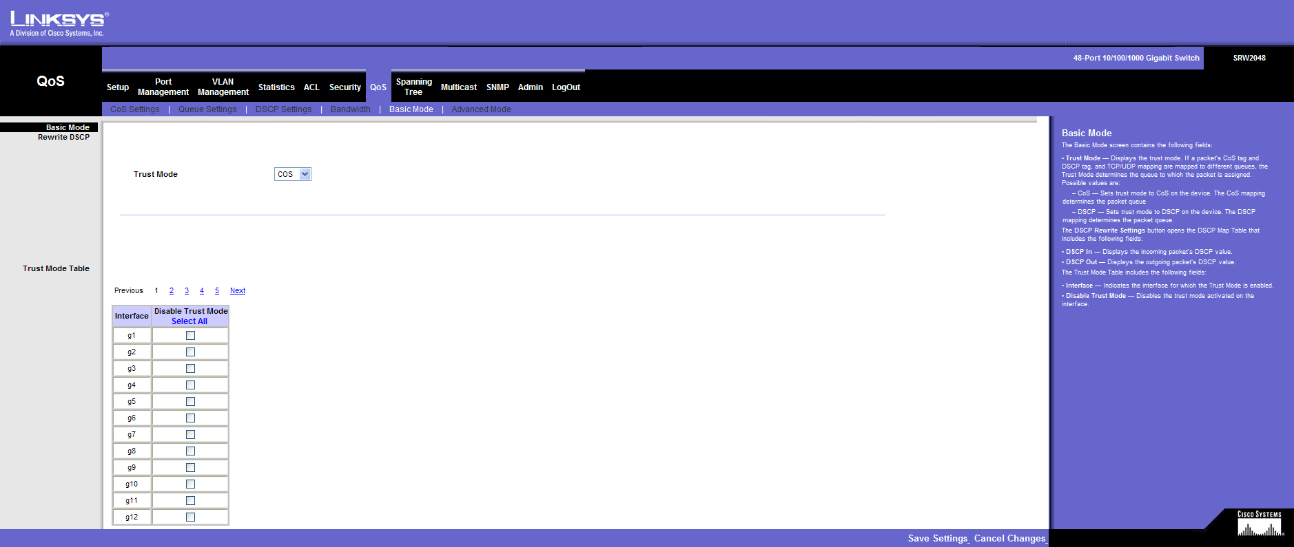
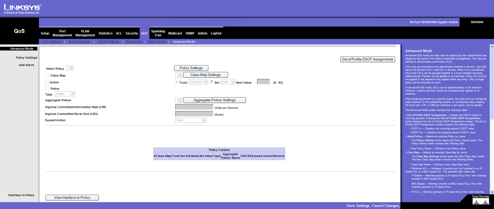
QoS
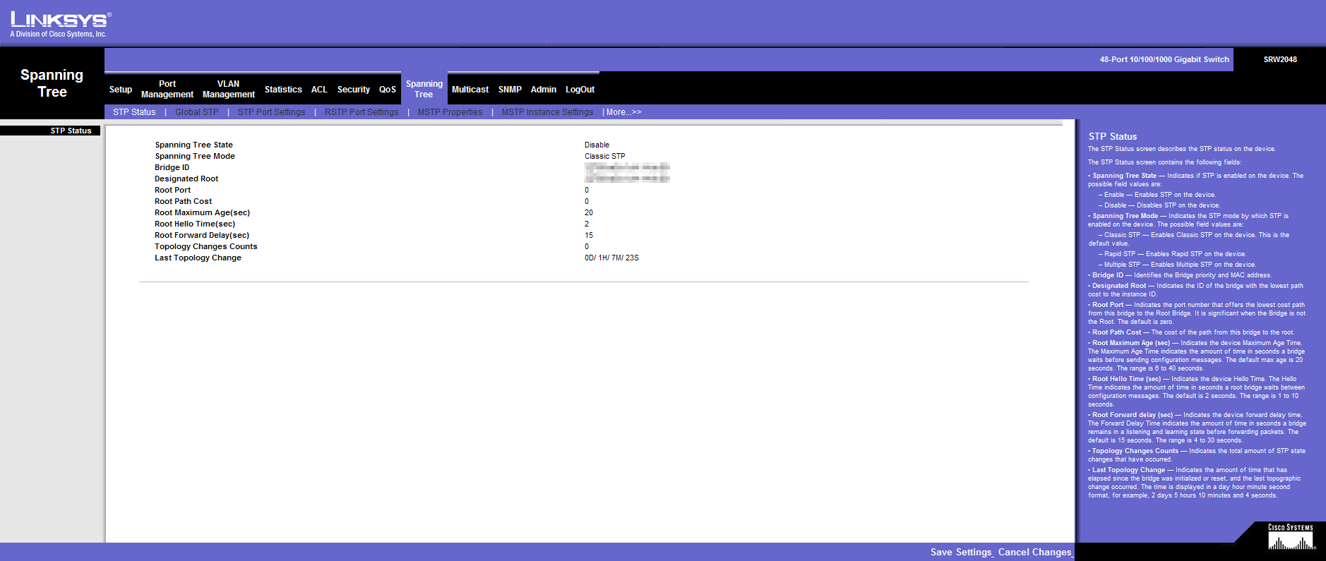
Spanning Tree
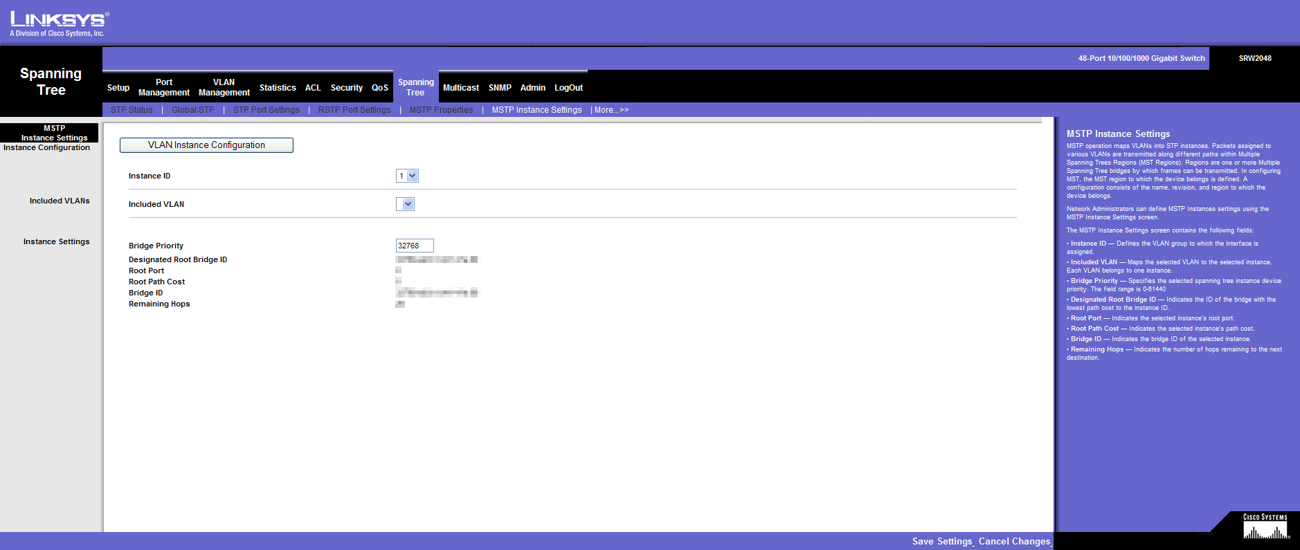
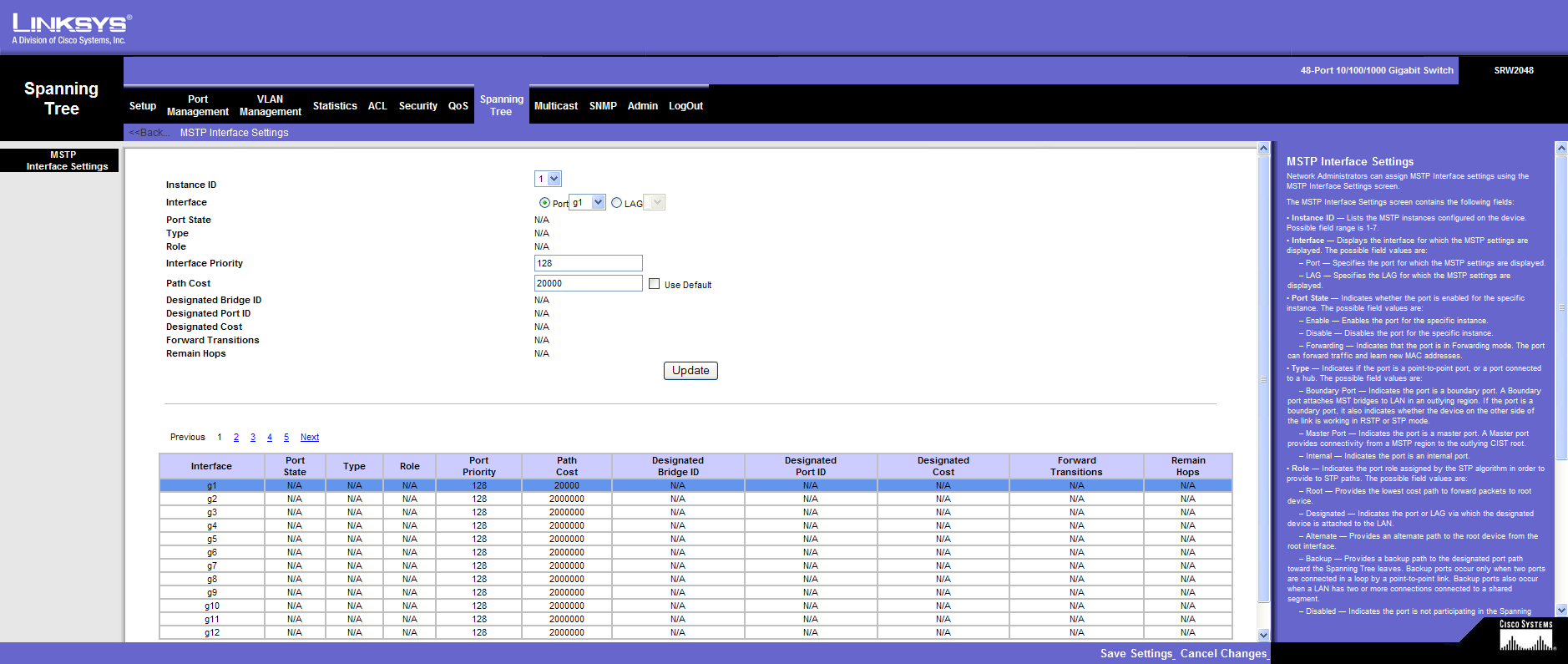
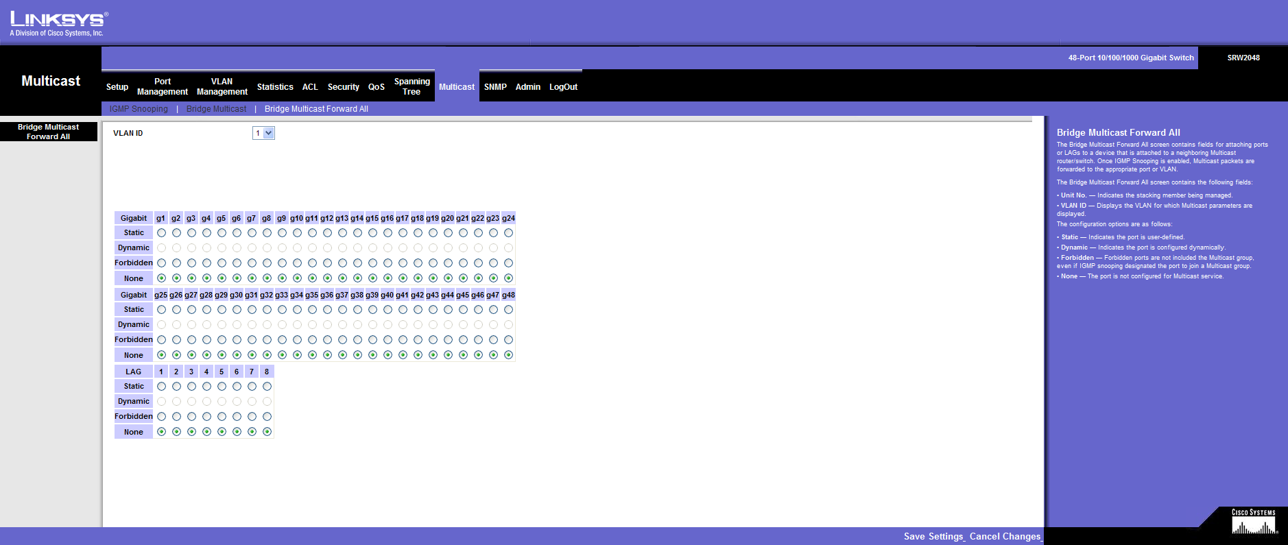
Multicast
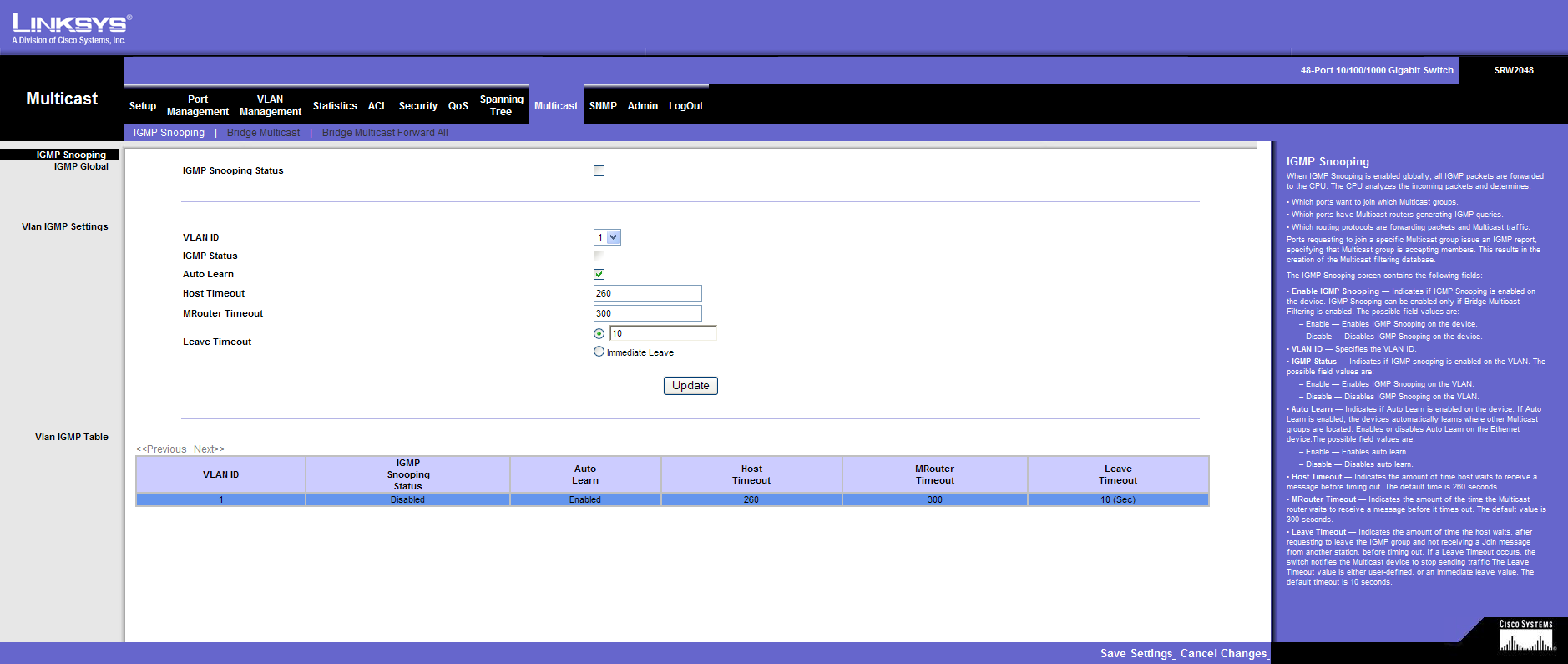
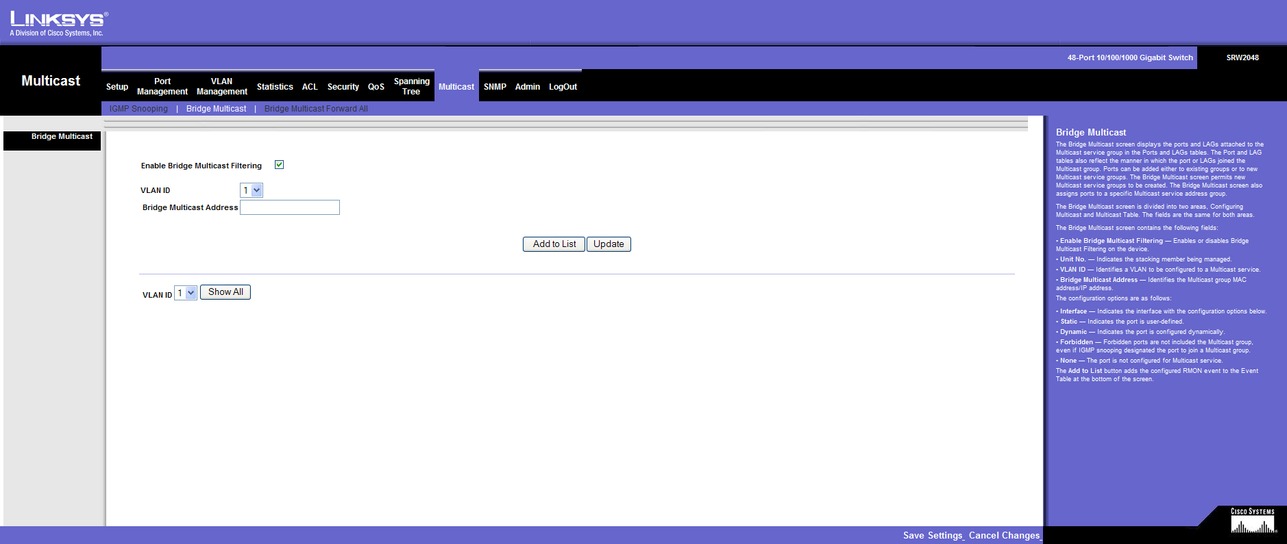
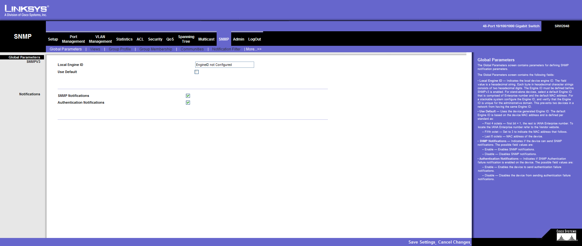
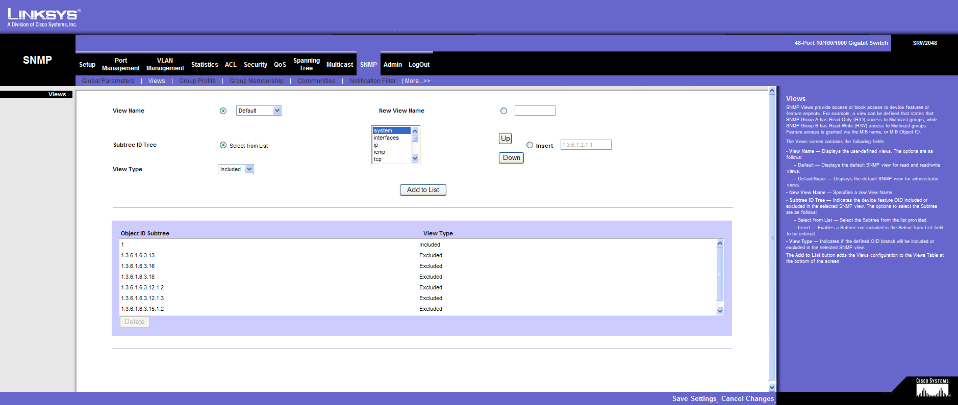
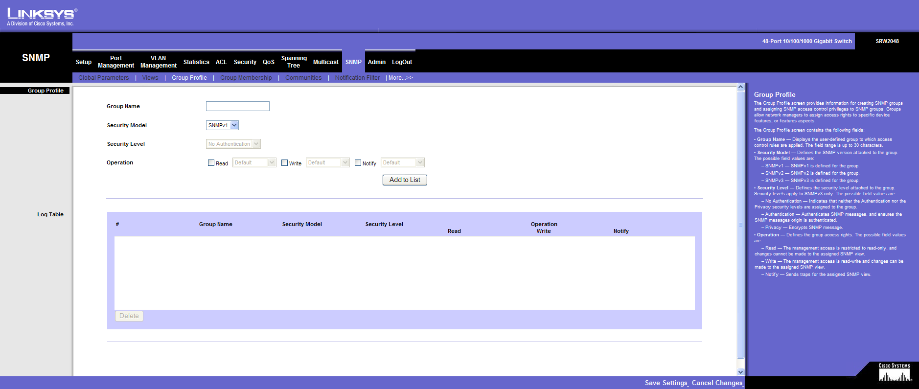
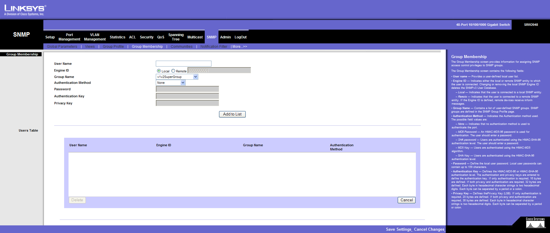
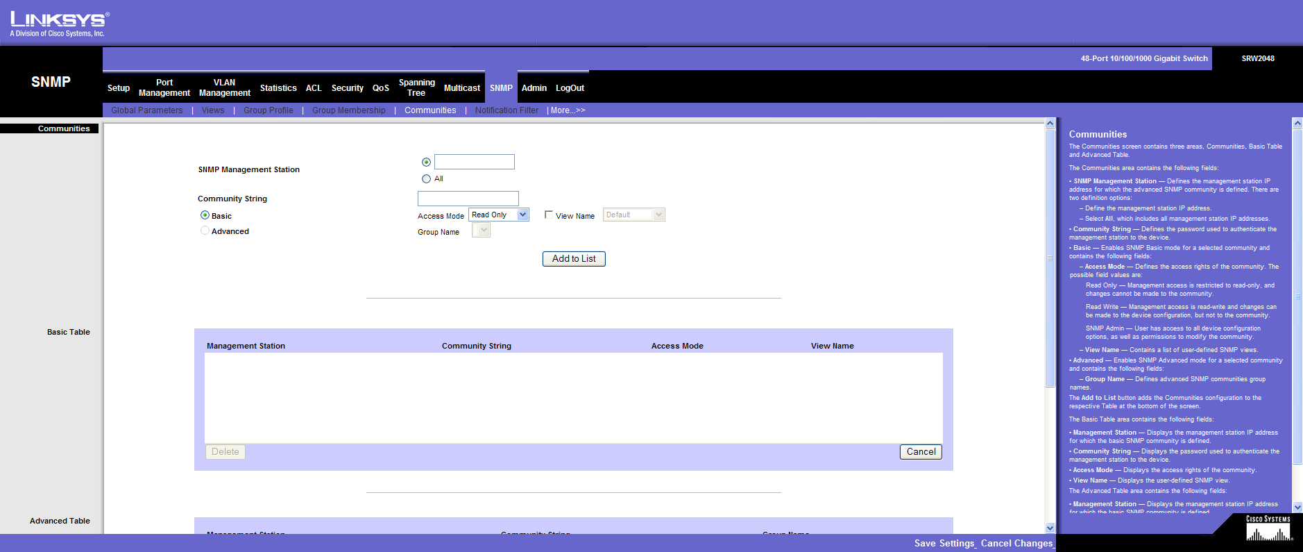
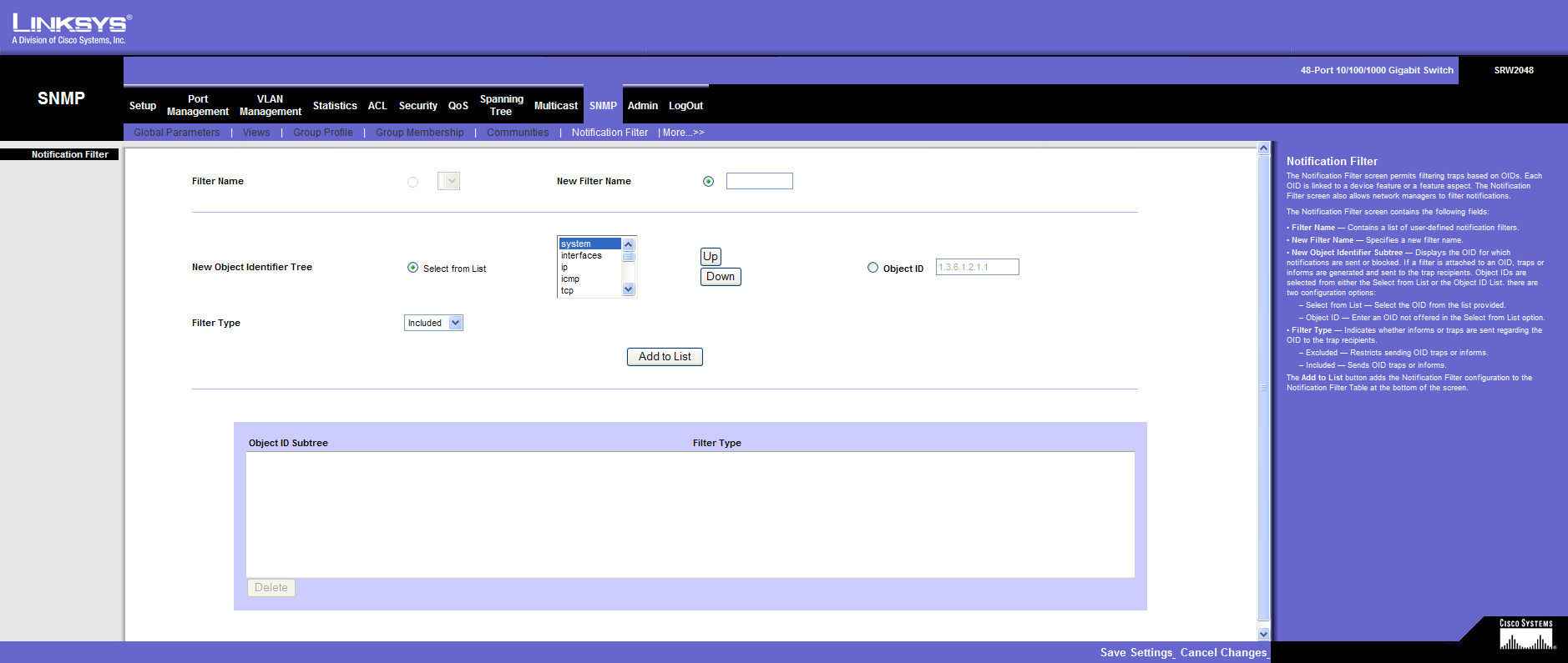
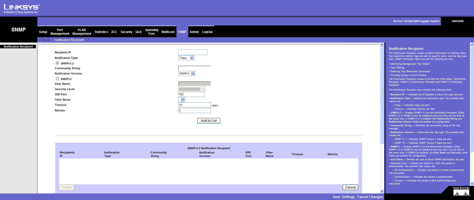
SNMP
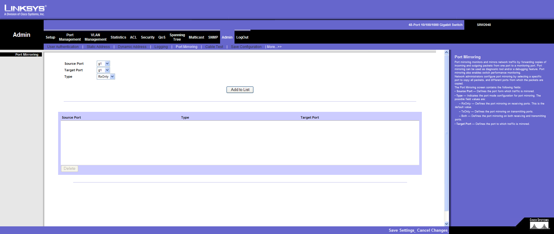
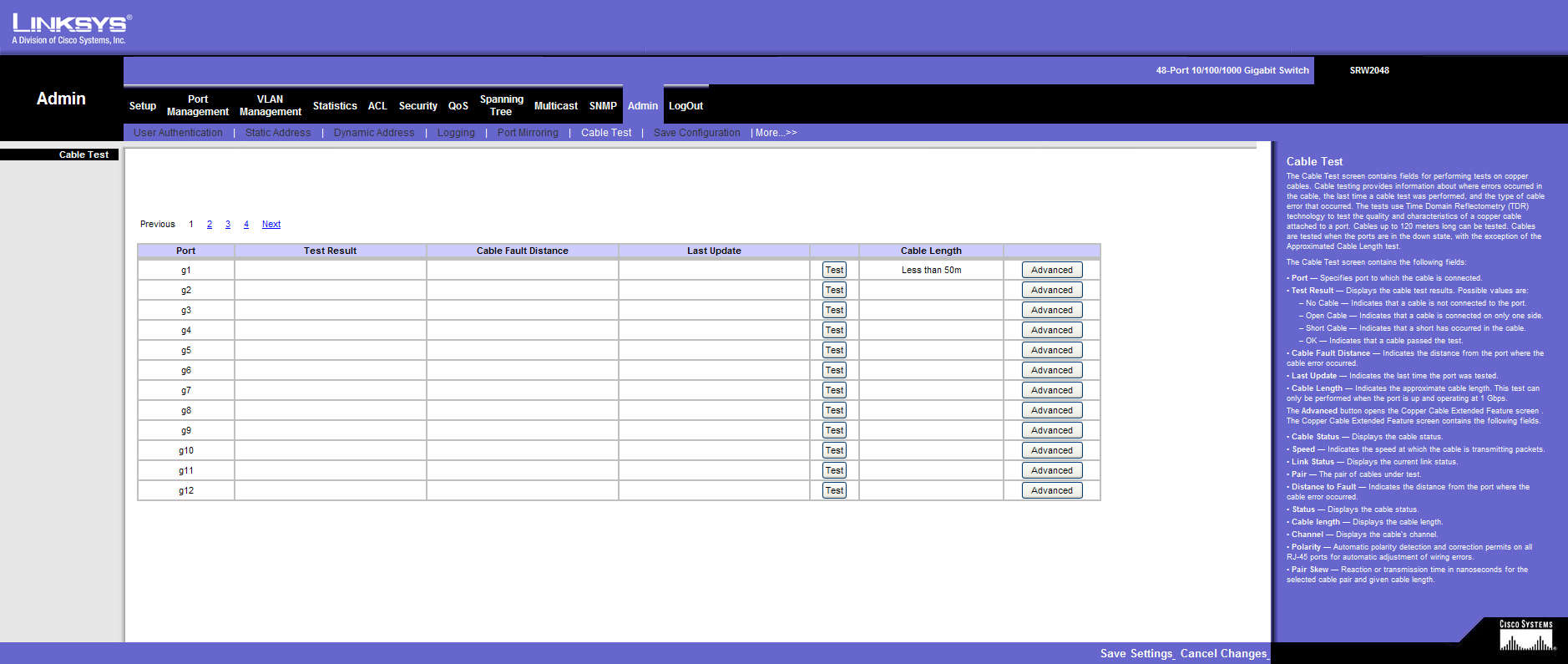
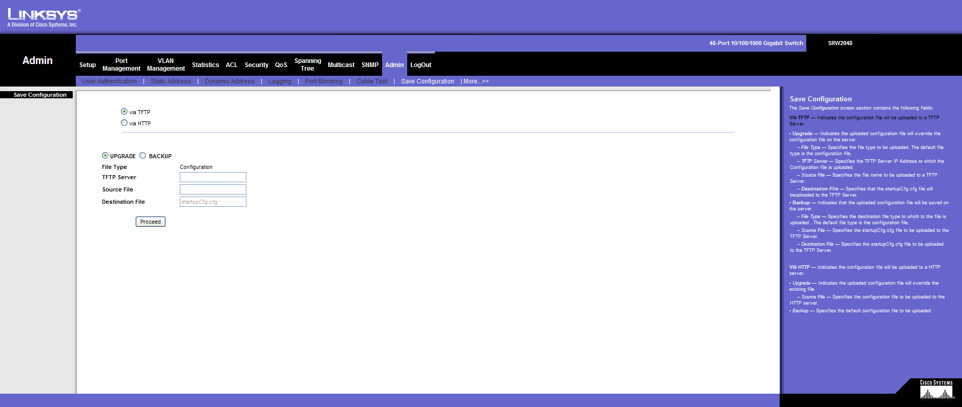
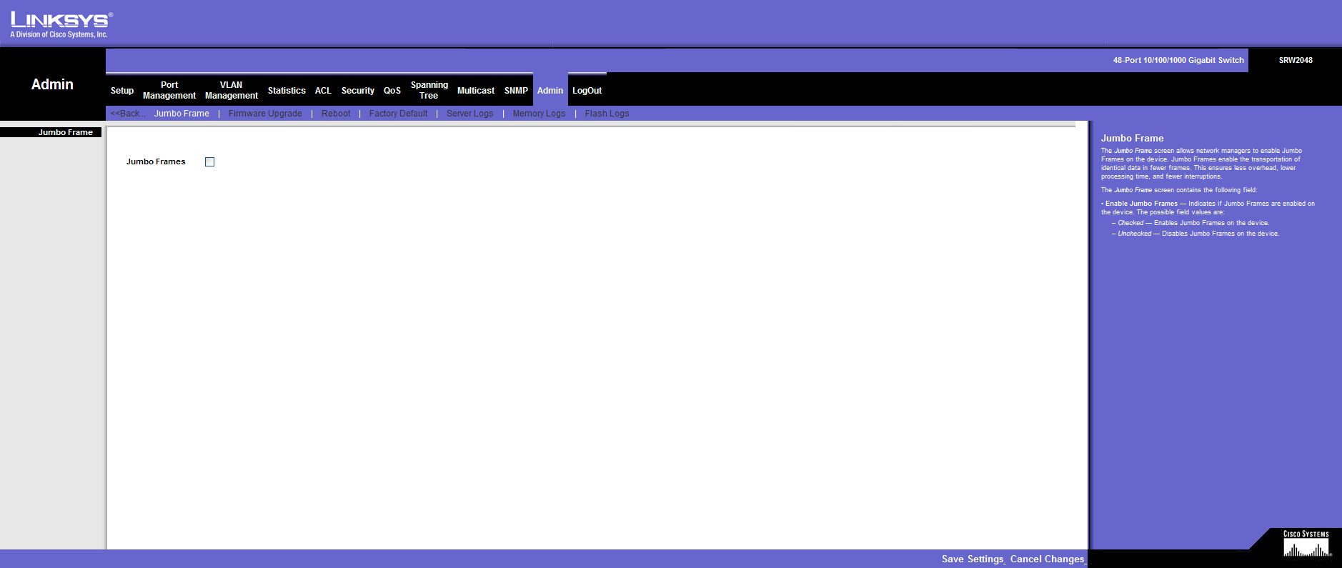
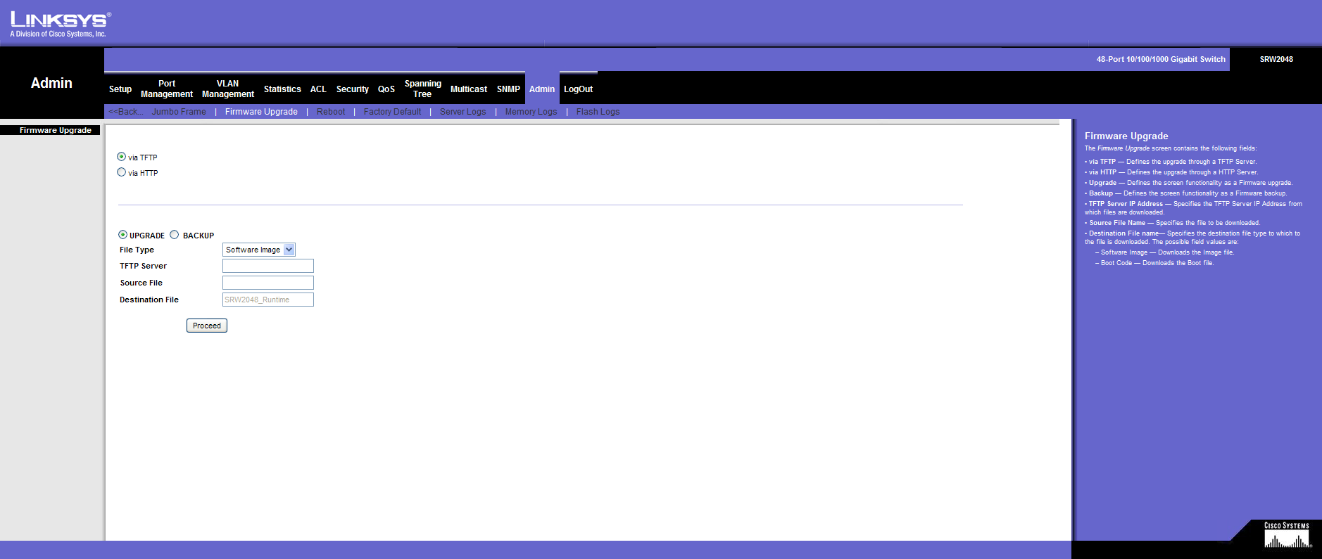
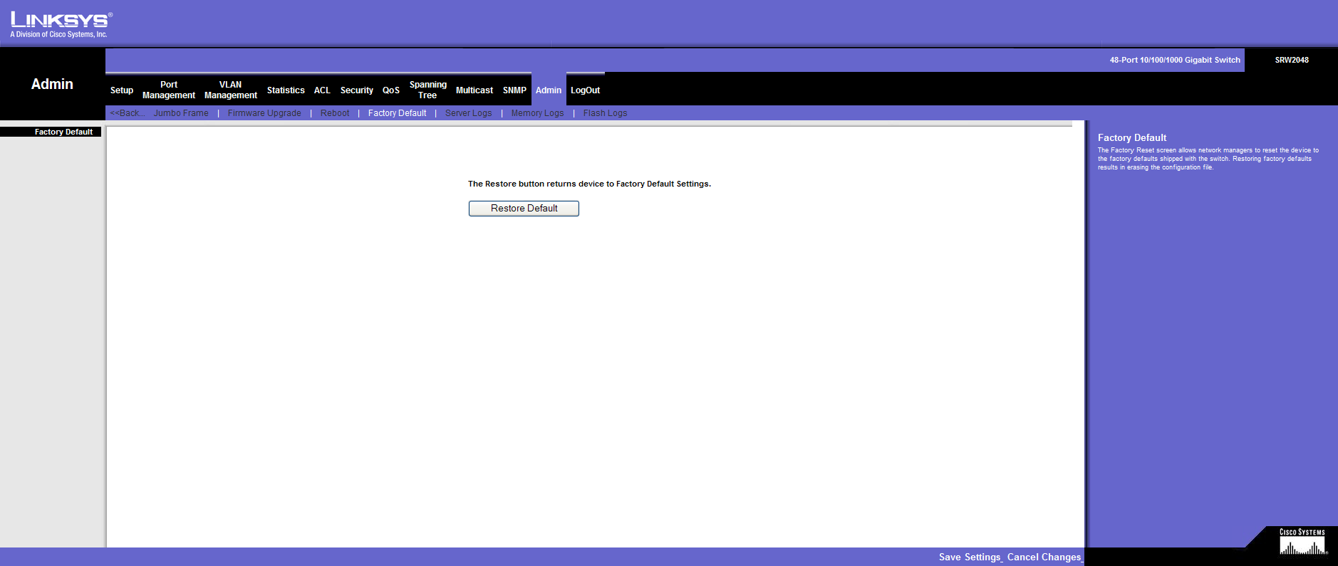
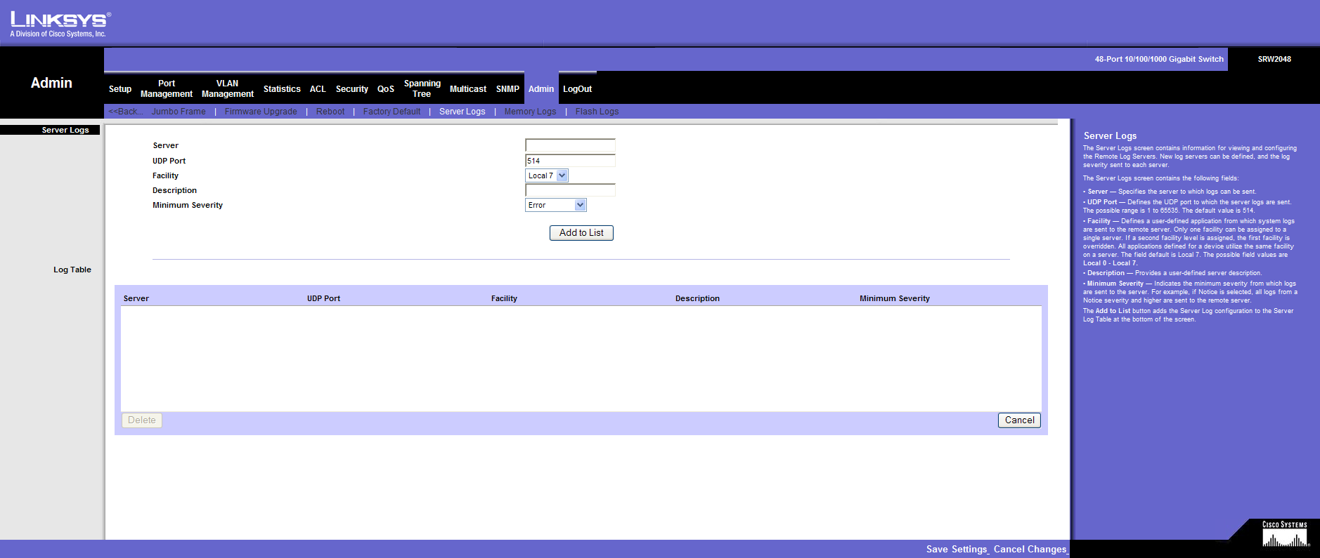
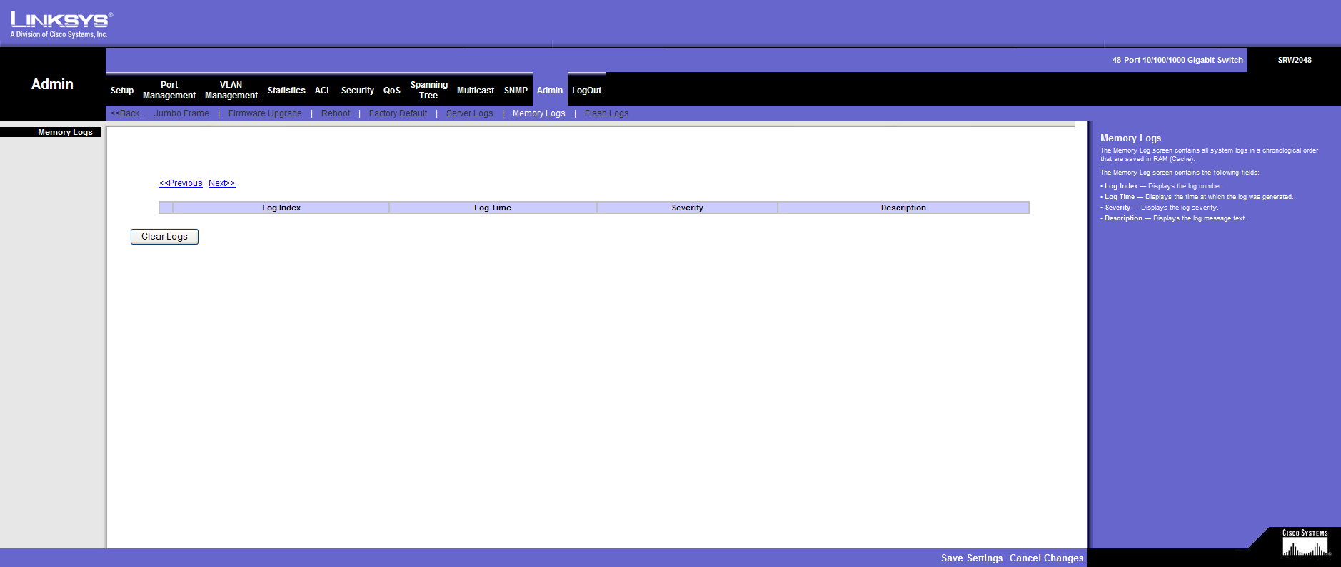
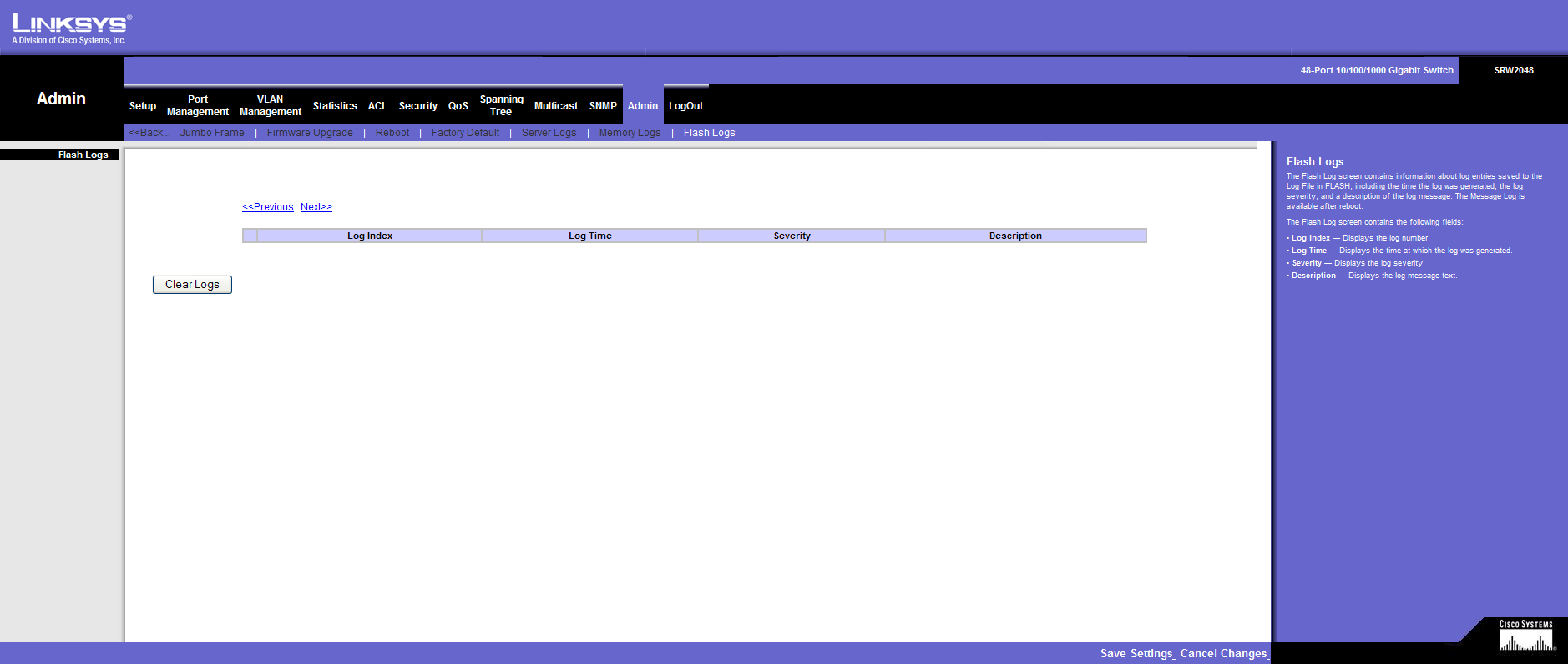
Admin

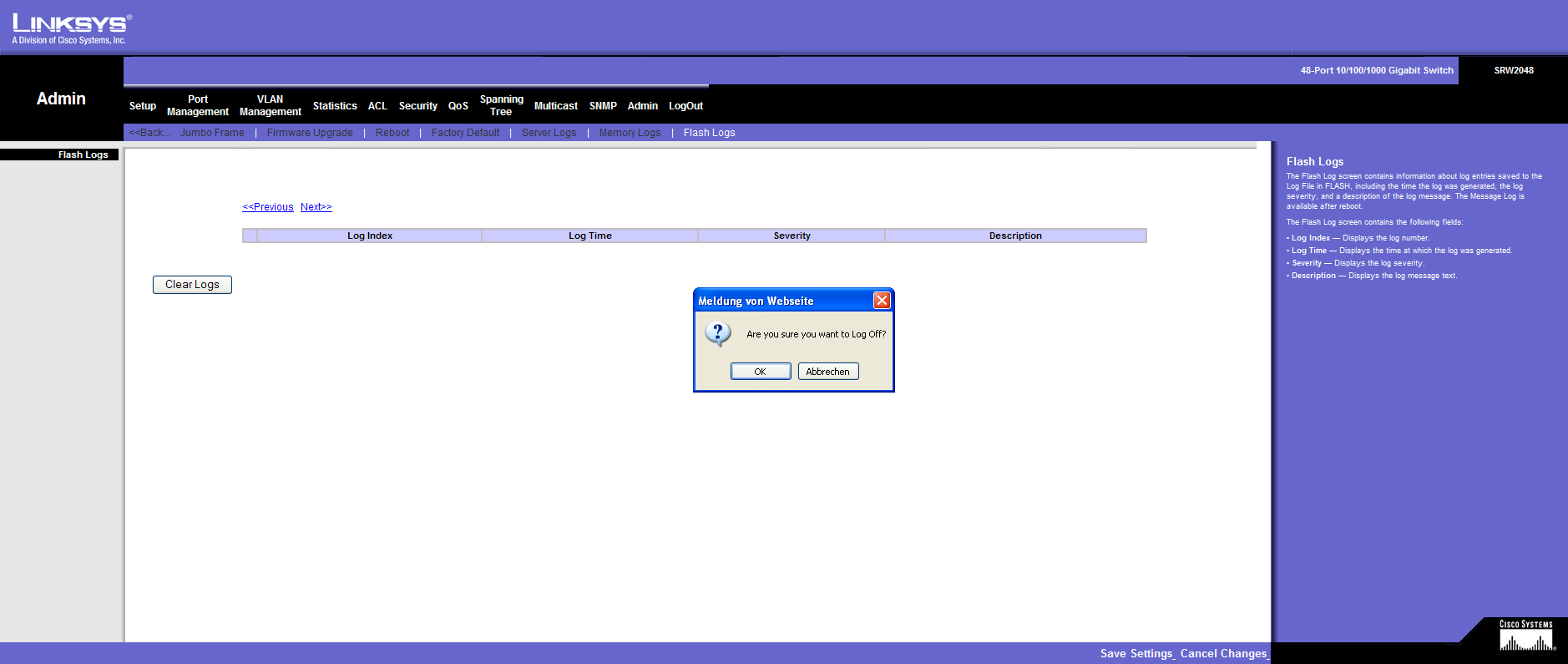
LogOut
This should ensure that every configuration option is documented in detail.