PTM or “Phase Transition Material” has been a recurring topic in the PC industry since at least 2022. Some manufacturers now use it as standard in their products (for example in certain Lenovo laptop models and in servers).
The reason to seek an alternative to traditional thermal paste* becomes particularly apparent in devices with high to very high power density (e.g. modern GPUs): the so-called “pump-out effect” occurs. Due to the cyclic heating and cooling of the silicon, the IHS and the heatsink, the simultaneous expansion and contraction of the material over time forces the thermal paste out, resulting in progressively poorer contact between the two components over time and a decrease in cooling performance.
This is why many recommend replacing the thermal interface material at least once a year if a device runs frequently and at its limits, as cooling performance noticeably and measurably declines. Thermal interface material therefore has the lowest thermal resistance immediately after it has been freshly applied or shortly thereafter. After that, cooling performance gradually deteriorates slightly with each cycle.
The other advantages and disadvantages of common TIMs, including PTM, can also be easily compared in a table:
| Thermal paste | PTM | Liquid Metal | |
|---|---|---|---|
| Manufacturer | Arctic | Honeywell | Thermal Grizzly |
| Product | MX-4* | PTM7950* | Conductonaut* |
| Thermal conductivity | up to 5 W / (m·K) | up to 8.5 W / (m·K) | up to 73 W / (m·K) |
| Temperature range | -50 °C to +150 °C | -40 °C to +125 °C The phase transition occurs at approximately 45°C | +10 °C to +140 °C |
| Durability | Chemically and technically moderate; technically rather short due to high power transfer as pump-out occurs | Chemically and technically long | Chemically and technically very long under optimal conditions |
| Pump-Out Effect | Yes | No | No |
| Electrically conductive | No | No | Yes |
| Optimal surface finish | All | All but the best performance is only achieved with direct-die cooling | Only nickel-plated copper makes sense in the long run, since the indium in the liquid metal gradually diffuses into the material over time |
| Effort | Low | Mid | High |
| Application | Simple | Rather difficult | Average if you follow the instructions |
| Cost | Low to mid | Mid | High |
Just give it a try!
Just like with liquid metal back then, I’ve wanted to try out this PTM from Honeywell ever since I first read about it. The advantages are obvious:
- No pump-out
- Theoretically no future maintenance required
- Slightly better heat transfer than thermal paste
- No risk of short circuits or the high effort necessary for liquid metal (or surface corrosion over time)
There are also some drawbacks, though; for example, you need to run through a few full temperature cycles to reach full performance. That should be the least of your worries, though. It’s also not exactly convenient to use.
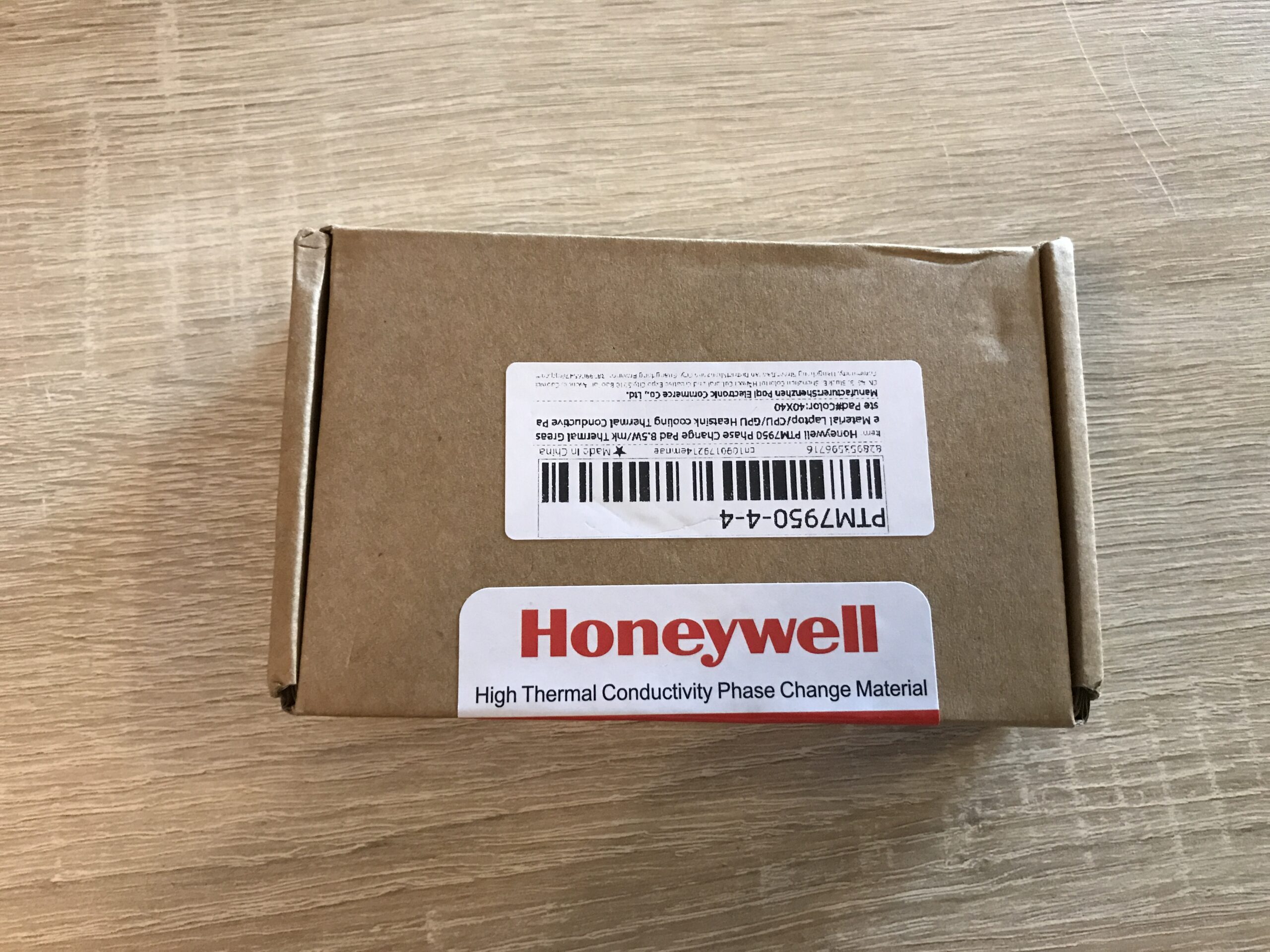
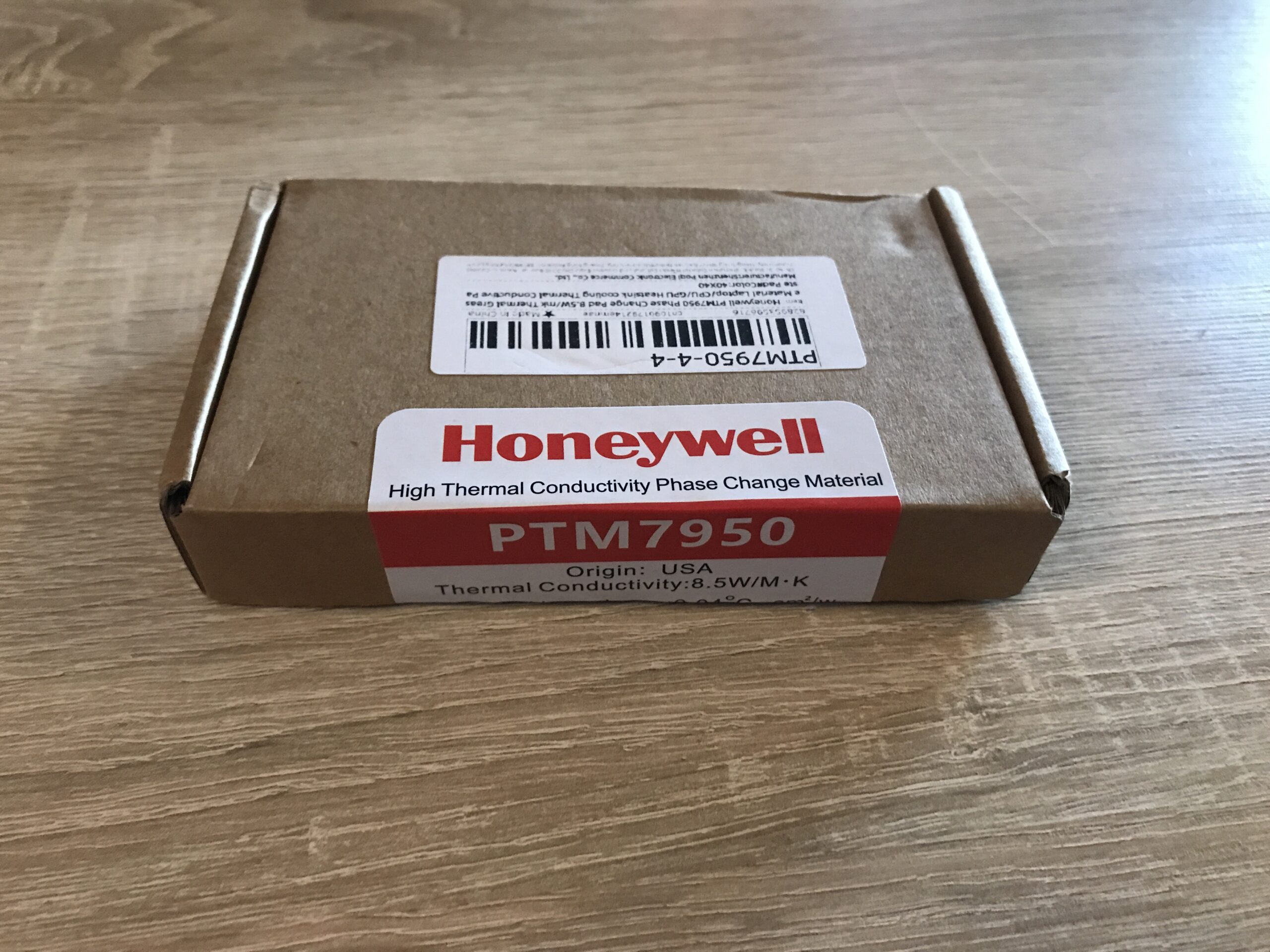
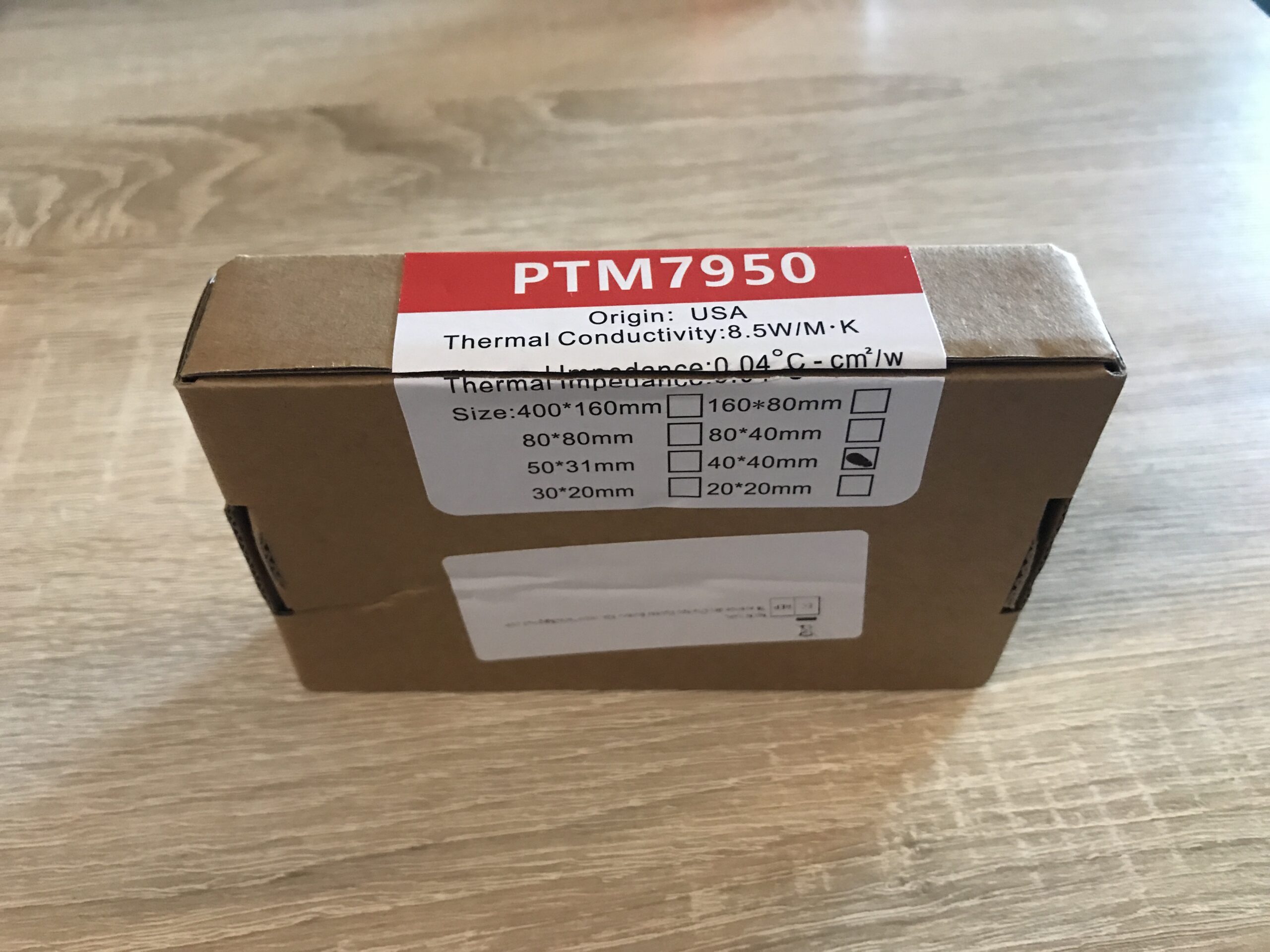
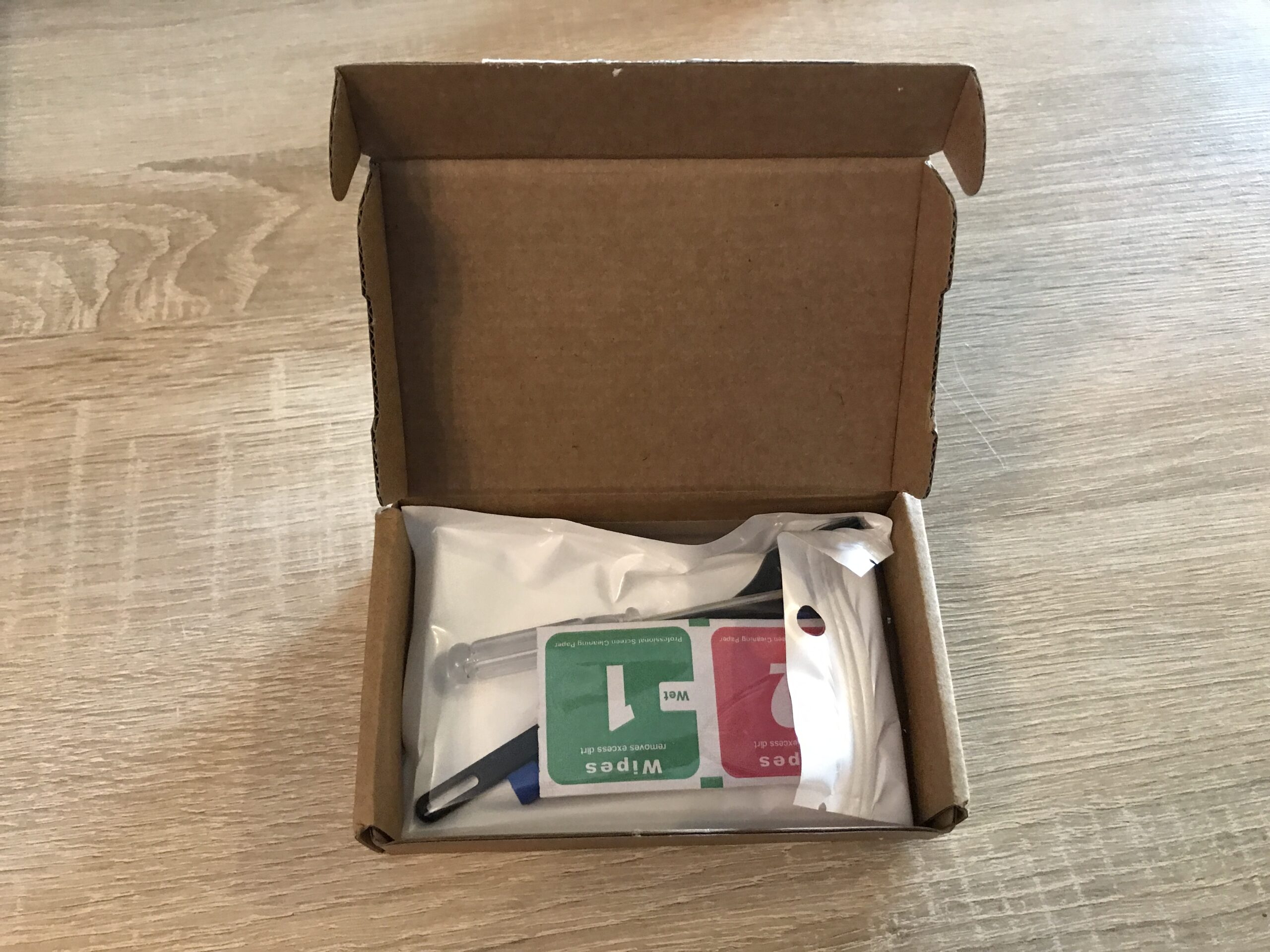
I recently purchased two units of the 40 x 40 mm version at a good price from a reputable seller on AliExpress*. This size fits the heatspreaders of all older and newer Intel and AMD desktop processors (but not the large server or workstation CPUs!).
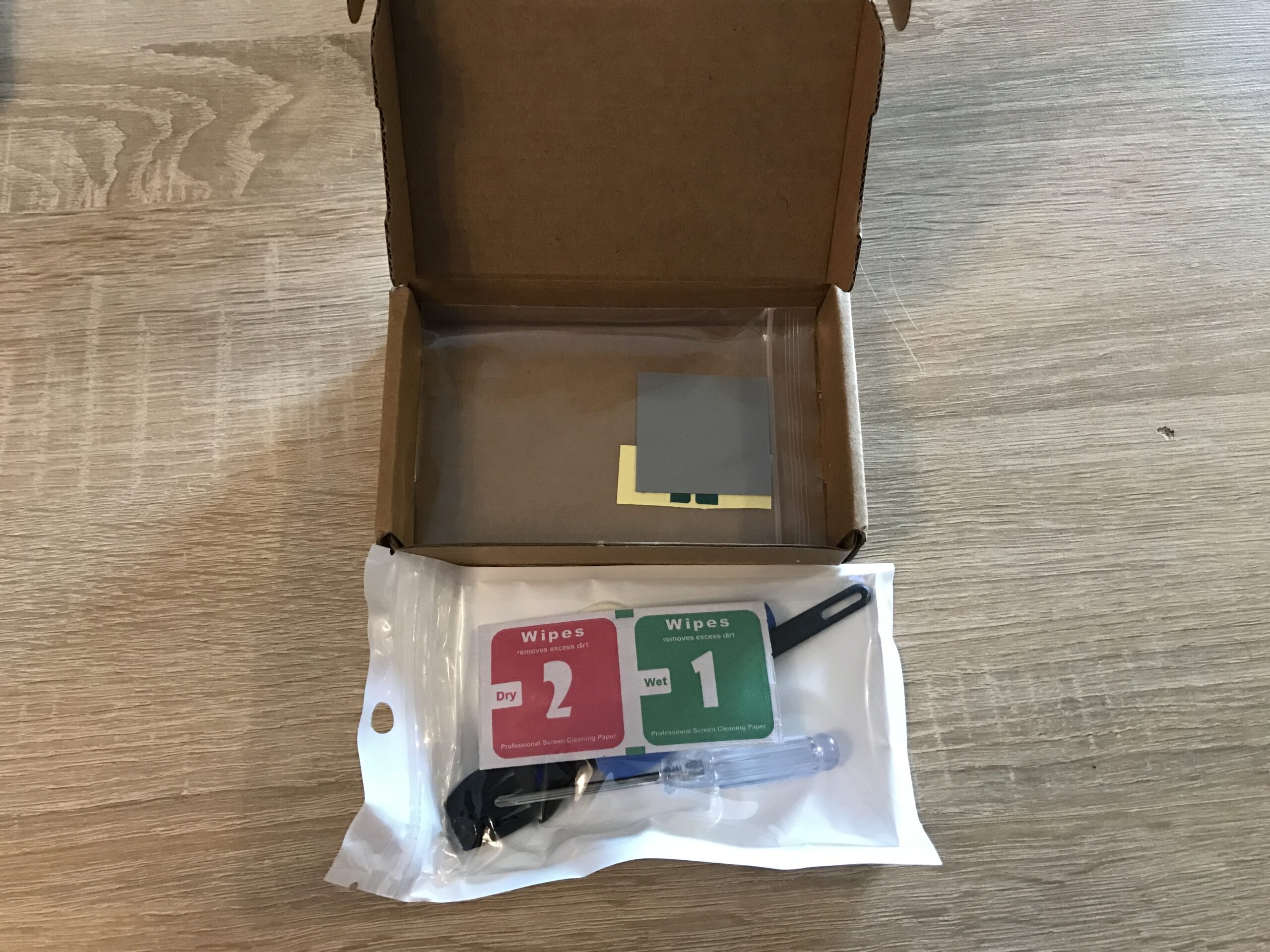
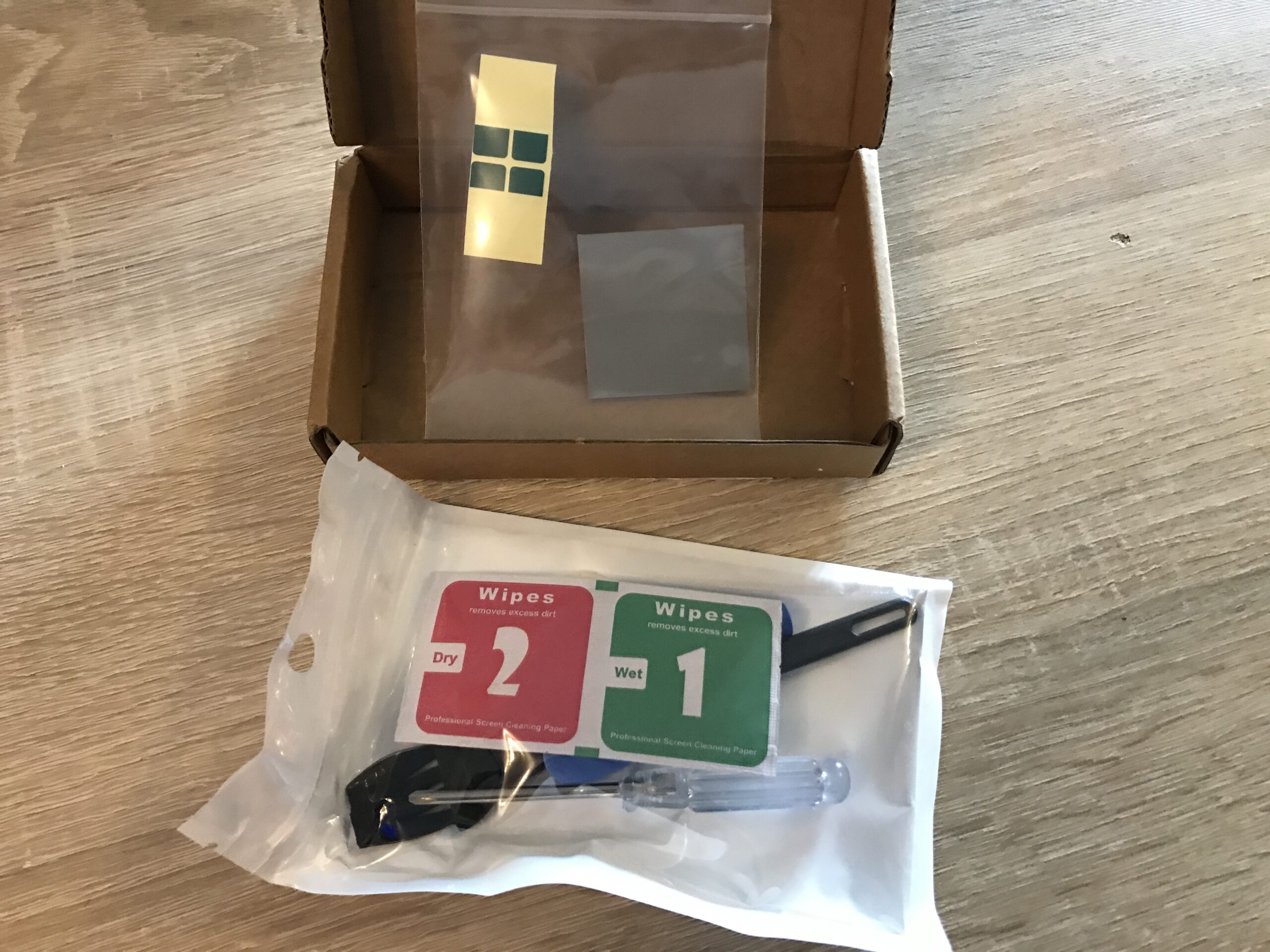
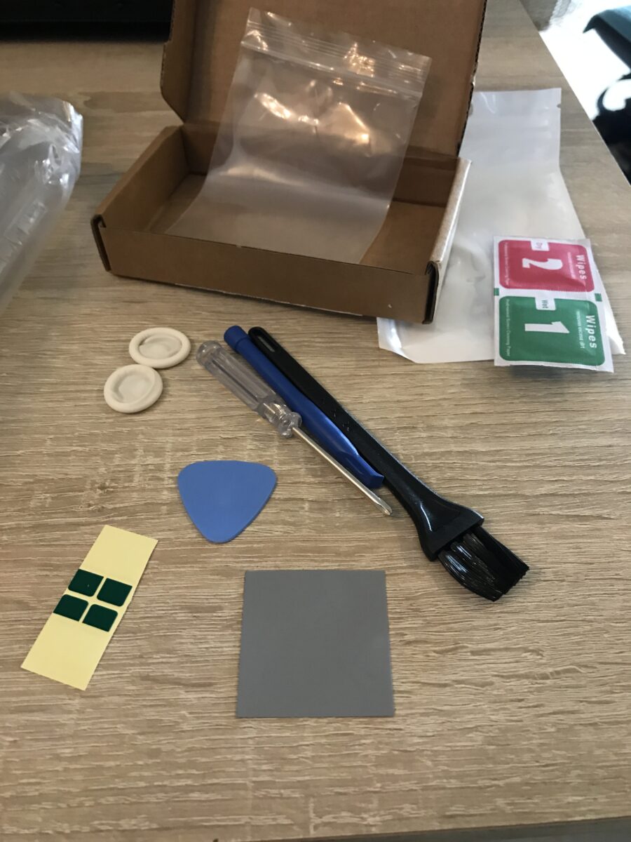
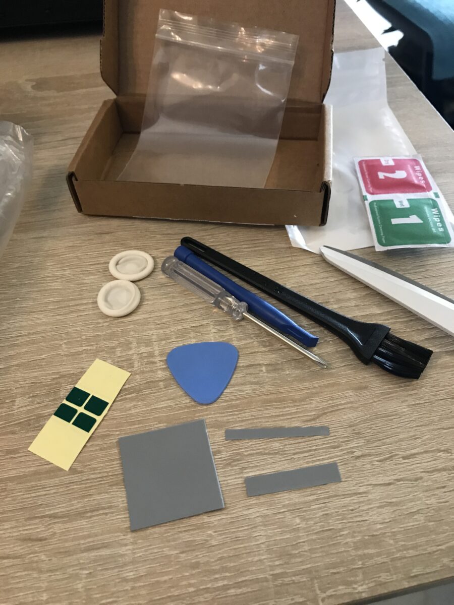
The whole thing came as a set with everything you need:
Intended Use, or: The Victim
Ideally, the PTM would be used with direct-die cooling, meaning the silicon die is in direct contact with the cooler rather than through an additional “Integrated Heat Spreader” (IHS).
Since desktop and server processors typically always come with an IHS, I’ll have to test the PTM in this suboptimal scenario for better or worse:
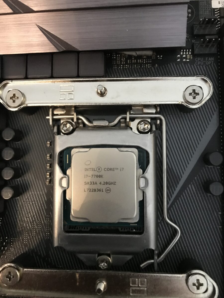
The processor in the “Küche-PC” – a max overclocked, air-cooled Intel Core i7-7700K – will be the first test subject. First, because I could do without this system if necessary and second because access to the hardware is very easy right now. By running it at the limits of voltage and cooling I should be able to see and measure significant differences, despite the IHS.
First off, it should be noted that this CPU was delidded some time ago, treated with Thermal Grizzly Conductonaut* and resealed with Elring Dirko HT* to replace the very poor-quality thermal paste used by Intel at the factory between the die and the heat spreader. I wrote a series of posts back then about the entire “Küche-PC” project, which also describes the delidding process in detail. So this post is about the second interface between the heat spreader and the cooling solution.
Currently, the hardware is temporarily installed in a used Corsair Graphite Series 230T case without any internal fans:
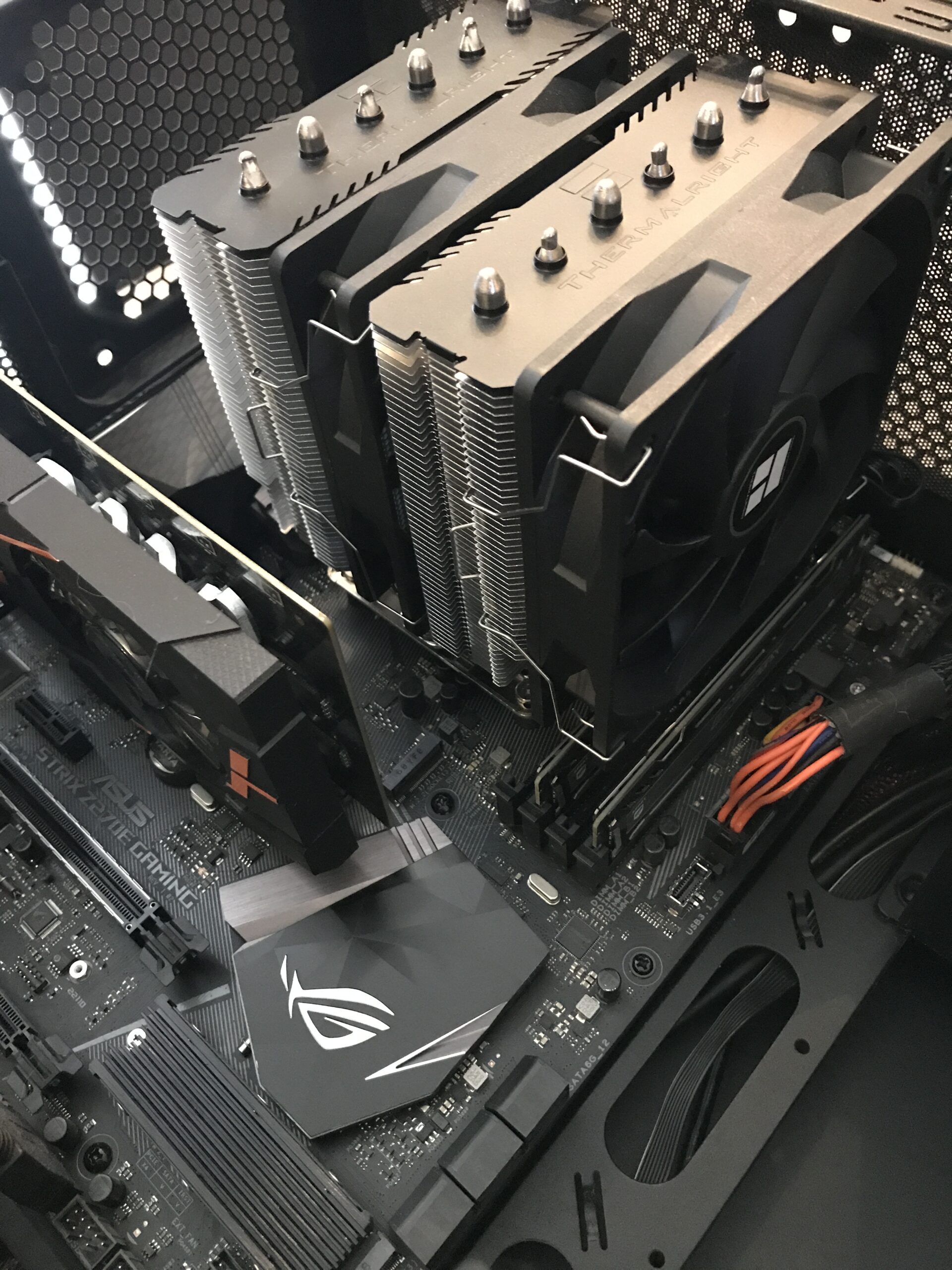
To remove the Thermalright Peerless Assassin 120 SE* I had to take out the motherboard – there just wasn’t enough room. As it turns out, that was a wise decision.
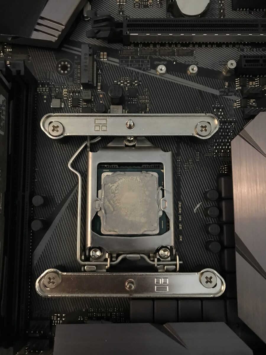
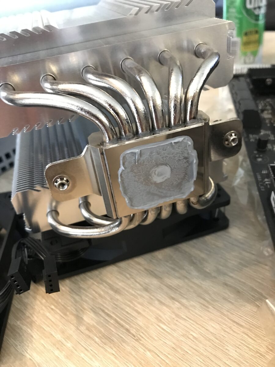
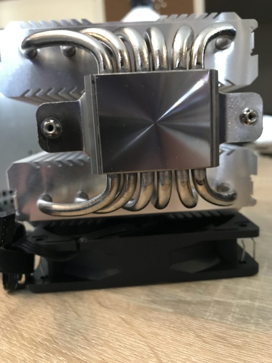
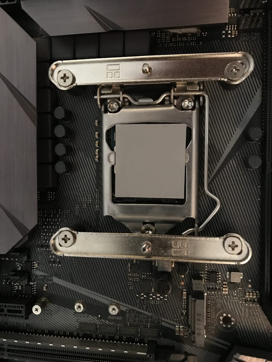
Removing the cooler and cleaning it
Now that accessing all the components had become much easier after removing the board, I took out the cooler and carefully cleaned all the parts first dry with paper towels and then with isopropyl alcohol* (instead of the wipes that came with the kit):
Let’s go…
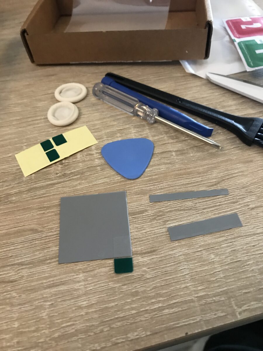
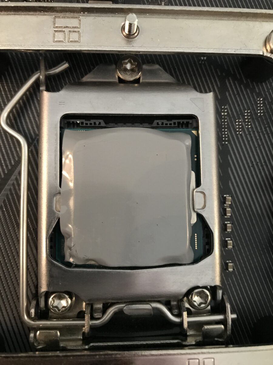
First, I unpacked the entire PTM kit and used a pair of sharp scissors to trim the 40 x 40 mm pad so it would fit the IHS of the i7-7700K a bit better, then I attached one of the included removal aids to one side:
Next, I attached a second peeling aid to the opposite side of the pad, peeled off one layer of film, carefully aimed, and “positioned” the pad on the heat spreader – if you can call it that, since it was essentially just dropped in place and has to stick there permanently because the adhesive bond is very strong right away and the risk of damaging the pad is very high. Then I peeled off the second, upper protective film, where you can see from the slightly damaged corner of the pad that this was anything but easy (second photo, bottom left).
At this point, it would have been advisable to cool the pad beforehand, as is often recommended, but I deliberately wanted to try it without doing so. It worked, but it wasn’t fun. Next time, I’ll cool the PTM for 10 – 15 minutes beforehand. The “holes” were visible air pockets, which I pricked with a needle so I could squeeze the air out:
After that, I carefully reinstalled the cooler, attached the fans, plugged them in and put everything back into the case.
First impression
I actually wanted to start recording with HWiNFO right from the first 45°C phase transition: However, the cooling performance was a few degrees Celsius worse than before, which resulted in several blue screens as soon as the system was under full load. The hottest core reached between 90°C and 100°C; previously, I had never seen 90°C or higher under the same conditions.
So, over the course of two days, I ran 5 cycles consisting of the following steps on the side to get a proper “burn-in” – after all, it’s well known that the PTM7950’s full cooling performance can only be achieved through burn-in:
- 10 minutes of idle time
- 30 minutes of Cinebench R23 Multicore
- 10 minutes of idle time
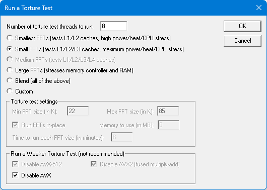
- 10 minutes of Prime95 without AVX (overclock is not AVX-stable)
- Turn off the PC and let it cool down for at least one hour
In the end, I ran Prime95 without AVX for several hours, and there were no further issues, crashes, or similar problems. This shows how the cooling performance has improved, but also how close this overclock is to its limits, both thermally and in terms of voltage (5.2 GHz under load on 3 – 4 cores, 5.3 GHz under load on 1 – 2 cores at just under 1.40 volts Vcore with air cooling!).
The differences in detail
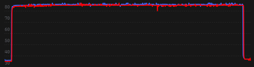
Before upgrading to the PTM, I used HWiNFO to record several 10-minute runs of Prime95 without AVX, each with a 20-second pre- and post-run to clearly see the ramp-up and ramp-down phases. I repeated this after the upgrade and the burn-in phase. In the end, I selected the most representative and average result from each set of three recorded measurements, and here I am comparing the various relevant values of an MX-4 run (blue) and a PTM7950 run (red). The system was warmed up for at least half an hour beforehand to achieve values that were as close to realistic as possible (Cinebench R23 Multicore, 30 minutes).
The thermal paste* had already been in use for several months at that point but had undergone significantly fewer than 100 cycles. If anything, there shouldn’t be much difference from freshly applied paste, especially since the system is normally operated far from heavy loads. As can be seen in the photos, there was also no significant “pump-out” visible yet (which occurs more frequently and intensely with direct-die cooling anyway).
I created the following comparisons from the graphs generated by HWiNFO logs using “Log Visualizer”:
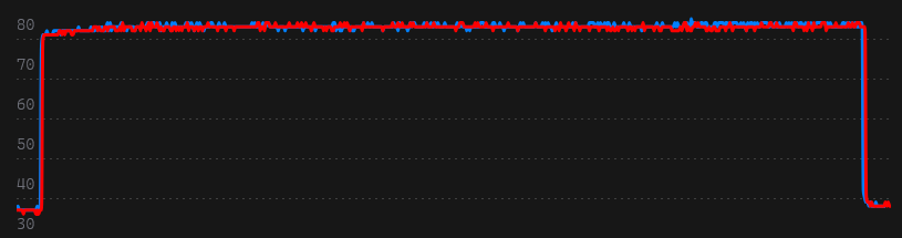
Temperature comparison of the first core
The three values in the table, from left to right, are: Minimum, Maximum, and Average. The values stated are in degrees Celsius.

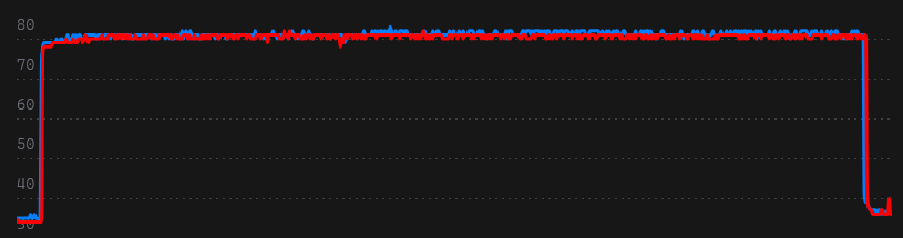
Temperature comparison of the second core
The three values in the table, from left to right, are: Minimum, Maximum, and Average. The values stated are in degrees Celsius.

Temperature comparison of the third core
The three values in the table, from left to right, are: Minimum, Maximum, and Average. The values stated are in degrees Celsius.


Temperature comparison of the fouth core
The three values in the table, from left to right, are: Minimum, Maximum, and Average. The values stated are in degrees Celsius.

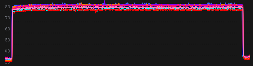
Temperatures of all cores combined
The three values in the table, from left to right, are: Minimum, Maximum, and Average. The values stated are in degrees Celsius.

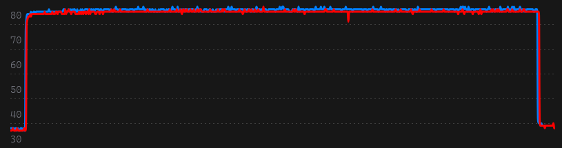
Temperature of the entire CPU
The three values in the table, from left to right, are: Minimum, Maximum, and Average. The values stated are in degrees Celsius.

Interim conclusion
Temperatures have improved across the board – slightly but measurably – and are outside the measurement tolerance range. What stands out is the nearly identical temperature distribution across the individual cores, regardless of which thermal interface material (TIM) is used between the IHS and the cooler: The liquid metal* is likely not distributed perfectly even on the die beneath the heatspreader, whether using paste or PTM. Even if it were, exactly identical values are likely never achievable for a variety of reasons, starting with the fluctuating silicon quality even within the die itself.
Next, we’ll move on to comparisons of power consumption and fan speeds.
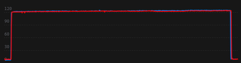
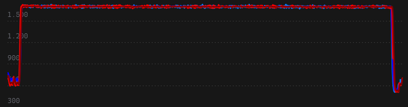
Total CPU power consumption
The three values in the table, from left to right, are: Minimum, Maximum, and Average. The values stated are in watts.

Fan speeds (2 x 120 mm from Thermalright, PWM)
The three values in the table, from left to right, are: Minimum, Maximum, and Average. The values stated are in revolutions per minute.

Conclusion
Since I’m not testing under laboratory conditions, the measurements won’t be 100% accurate because I can’t control factors like air pressure and room temperature. Nevertheless, I can draw a clear conclusion:
Even when used on a heatspreader, the PTM7950 is at least as good as high-quality thermal paste. In the measurements it was generally slightly better. Of course, there are also significantly more expensive thermal pastes and ones that are at least slightly better on paper than Arctic’s MX-4*. But regardless of which one, my primary goal was to prevent pump-out and, as a result, avoid maintenance on the cooling system (other than regular dusting).
Of course, I can’t say anything about the PTM’s medium- or long-term performance at this point. Also, the product I bought on AliExpress has the correct specs and a genuine-looking Honeywell logo but the pad inside could still be one of the many knockoffs out there now. It’s very hard to verify that with tools at home.
Personally, I’m satisfied with the result; if the cooling performance doesn’t decline, the change to this pad has done exactly what it was supposed to. If the opportunity arises, I’ll eventually apply the PTM to a very high-performance GPU die, where the results should be significantly better, especially in the long term.