
I consider delidding the processor to be one of the most important steps in this project.
EKWB describes the whole process well: EKWB (archive.org)
Firstly, you generally achieve much lower temperatures even with original clock speeds, and secondly, this greatly increases the scope for overclocking. At the same time, power consumption is reduced and the cooling system has to work less hard.
In my situation, it makes sense to do this first—before purchasing other necessary hardware. There is always the risk that the CPU will be irreparably damaged during delidding and the whole project will go down the drain, so it’s better not to buy anything that you won’t be able to reuse later.
What is required?
There are several different delidding tools available from various suppliers to minimize the risk of damage. I printed a tool myself and also ordered a very inexpensive one from China*, and ultimately used the Chinese one (die-cast aluminum, more stable than PLA). To securely but reversibly and heat-resistantly reattach the heat spreader after delidding, I used “Dirko HT*” from Elring, which is very well known in the automotive industry. I used this 3D-printed mold to press the parts together.
Ultimately, the inferior thermal paste used by Intel ex works should be replaced with something much more efficient. Liquid metal* is really the only option if you want to get the most out of it:
 ⧉ Thermal Grizzly
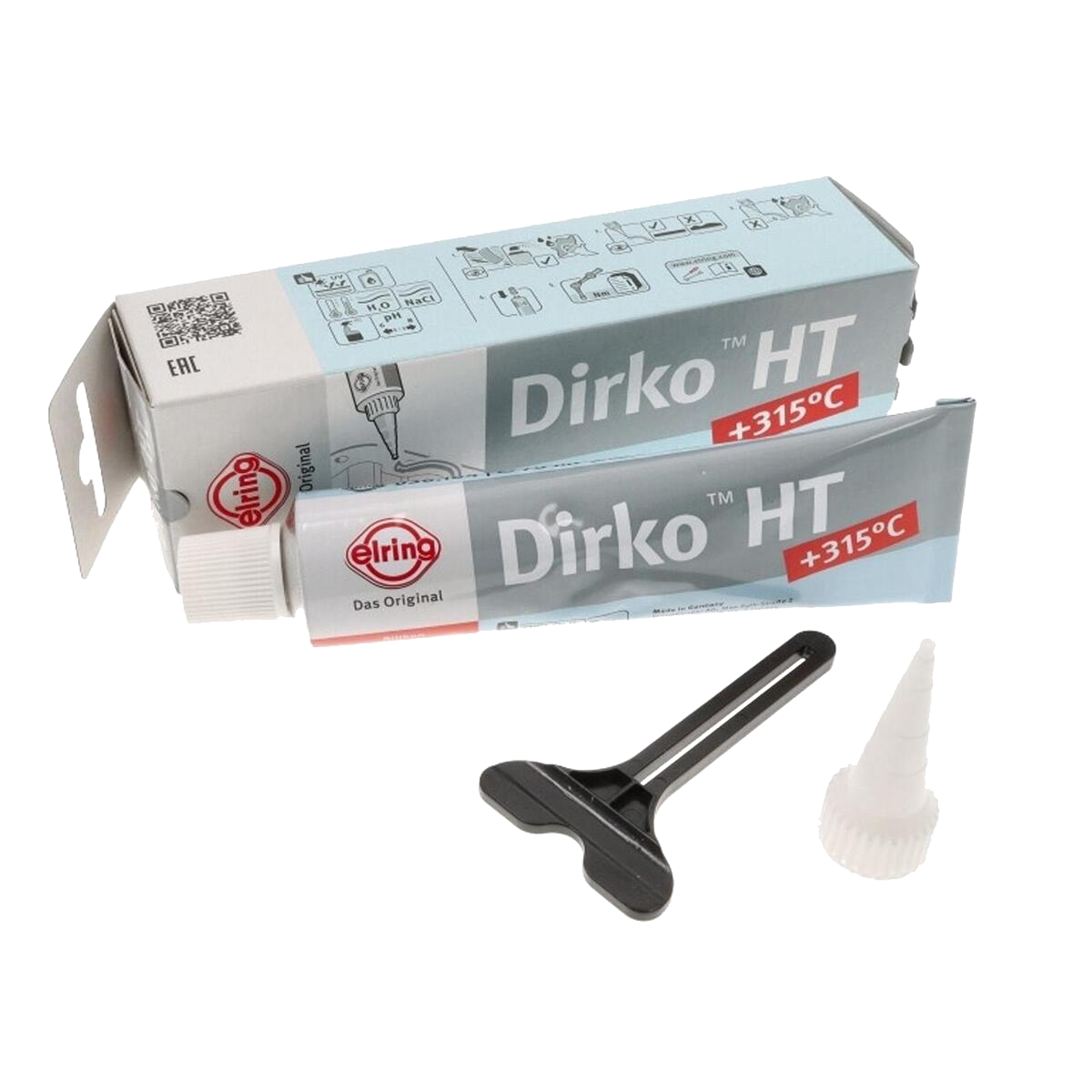 ⧉ Elring
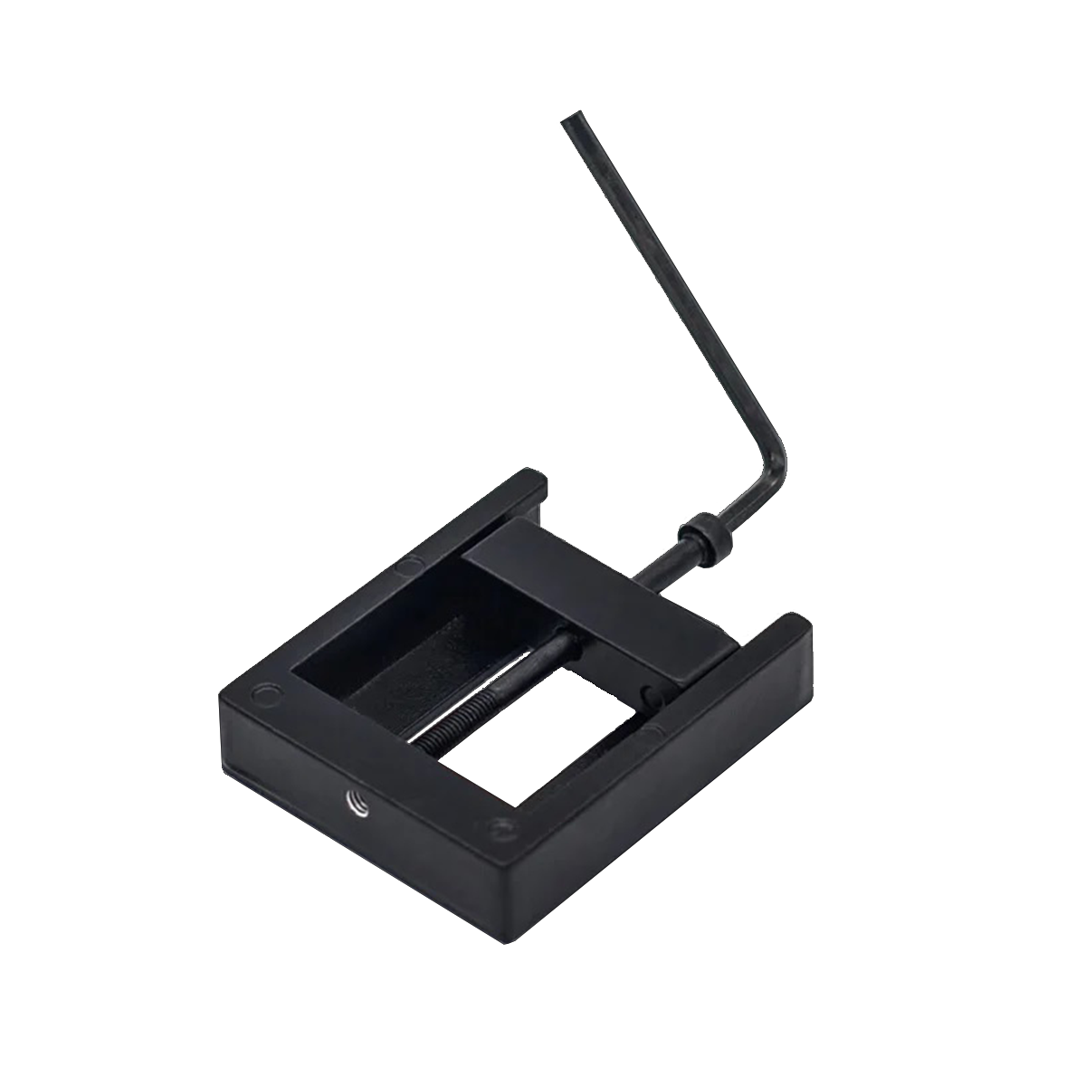
This will also be my first project using liquid metal, which has interested me for a long time—there just hasn’t been a really useful application for it until now, and it’s not exactly cheap. That’s about to change.
Let’s go…
First of all, it should be noted that you should proceed with extreme caution, as there are many small, sensitive SMD components on the underside of the CPU that could potentially be damaged.
With the necessary care, place the processor in the delid tool and screw it in by hand until the movable part slightly clamps the heat spreader. At this point, you should check carefully that the CPU is inserted correctly (the right way round!) and has enough space around it, then insert the Allen key provided into the screw head and continue screwing the screw into the tool. It should be difficult at first and then suddenly easy. When this point is reached, unscrew the screw, remove the slider again, and remove the CPU.
Don’t keep screwing when it got easier!
If you now carefully press between the heat spreader and the circuit board with your fingernails or a plastic spatula, the heat spreader should be easy to remove.
 ⧉ bit-tech
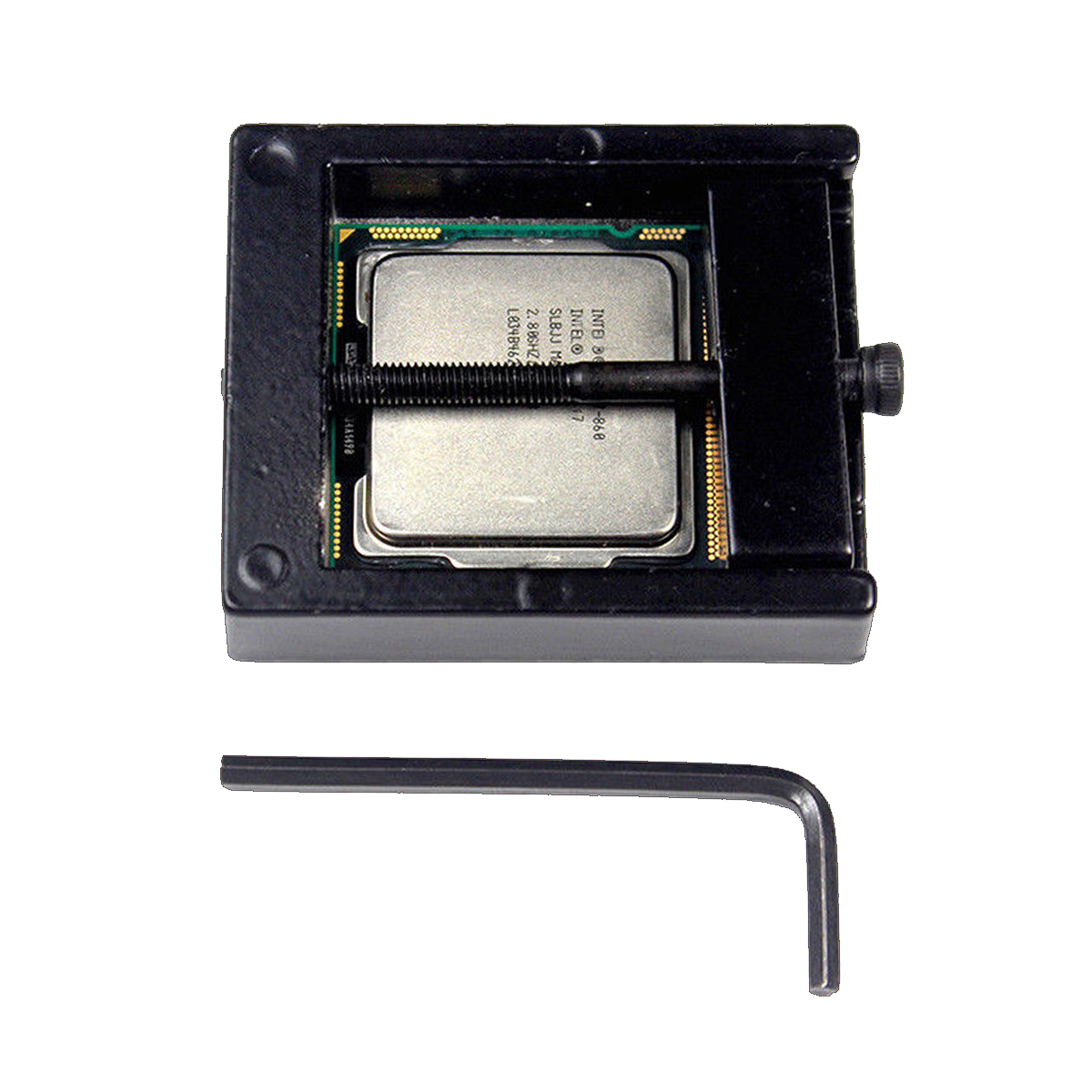
 ⧉ TechPowerUp
Cleaning:
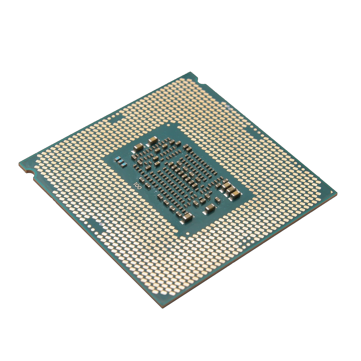
Now everything should be cleaned thoroughly. The black adhesive used by Intel, which is probably silicone-based, is stubborn. It is best to scrape it off the heat spreader with a plastic or wooden object. Of course, you should use something that is softer than nickel-plated copper (the material the heat spreader is made of) to avoid scratches or similar damage.
On the circuit board side, you have to do the same thing, but with extra care.
I scraped it off very carefully with my fingernails and “rubbed off” the remaining residue with isopropanol on a paper towel.
The thermal paste can be removed as usual with isopropanol*, nothing special.
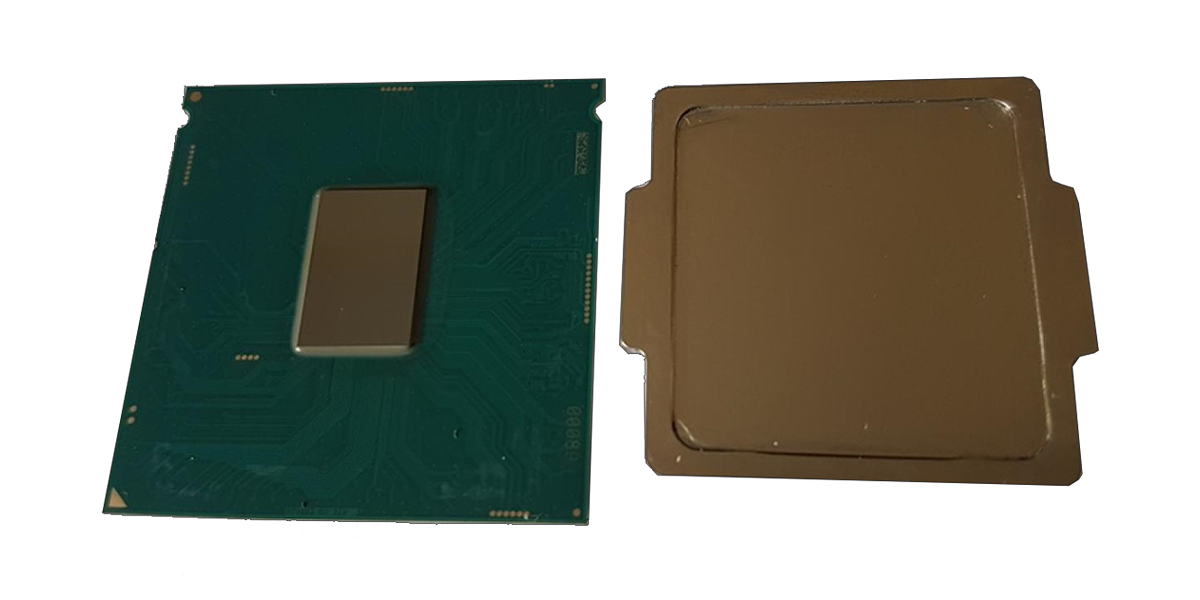
If the result looks like this, everything has gone well:
 ⧉ PCGH
Isolation:
Now the processor must be prepared for use with liquid metal. This means that all potentially conductive surfaces must be insulated, either with (nail) polish* or Kapton tape*.
I found polish to be safer and therefore coated all marked surfaces with nail polish:
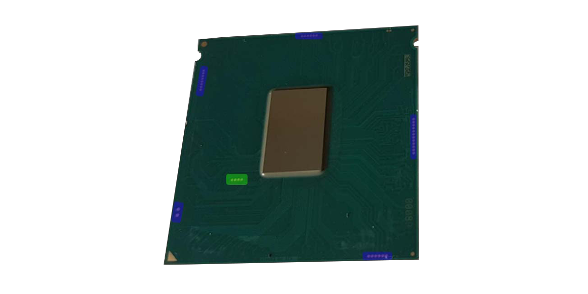
In retrospect, I would say that insulating the four contacts (marked in green) near the die with Kapton would have been sufficient. Since this was my first project with liquid metal, I proceeded with excessive caution.
Applying liquid metal:
Now comes the actual application of the liquid metal.
It is supplied in a syringe, together with cloths and a kind of special “cotton swab.”
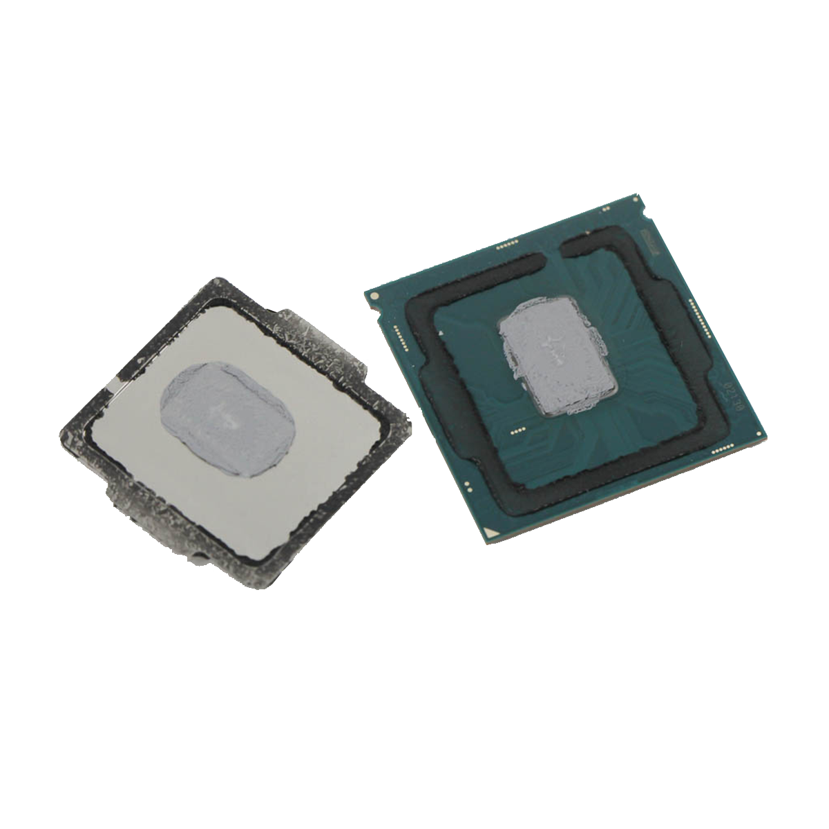
First, the processor is placed on a soft, flat surface and a small “ball” of liquid metal is applied to the center.
This is then spread over the die with the cotton swab using circular movements and a little pressure until it is evenly distributed.
I then spread a really thin line of Elring Dirko HT sealant over the heat spreader.
 ⧉ Phiarc
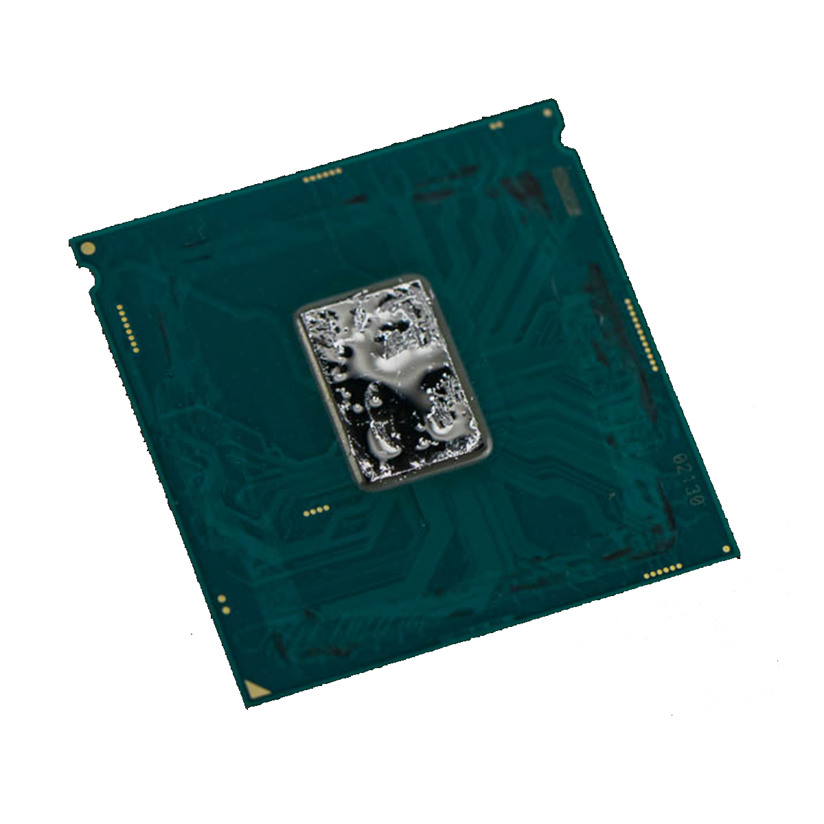 ⧉ TechPowerUp
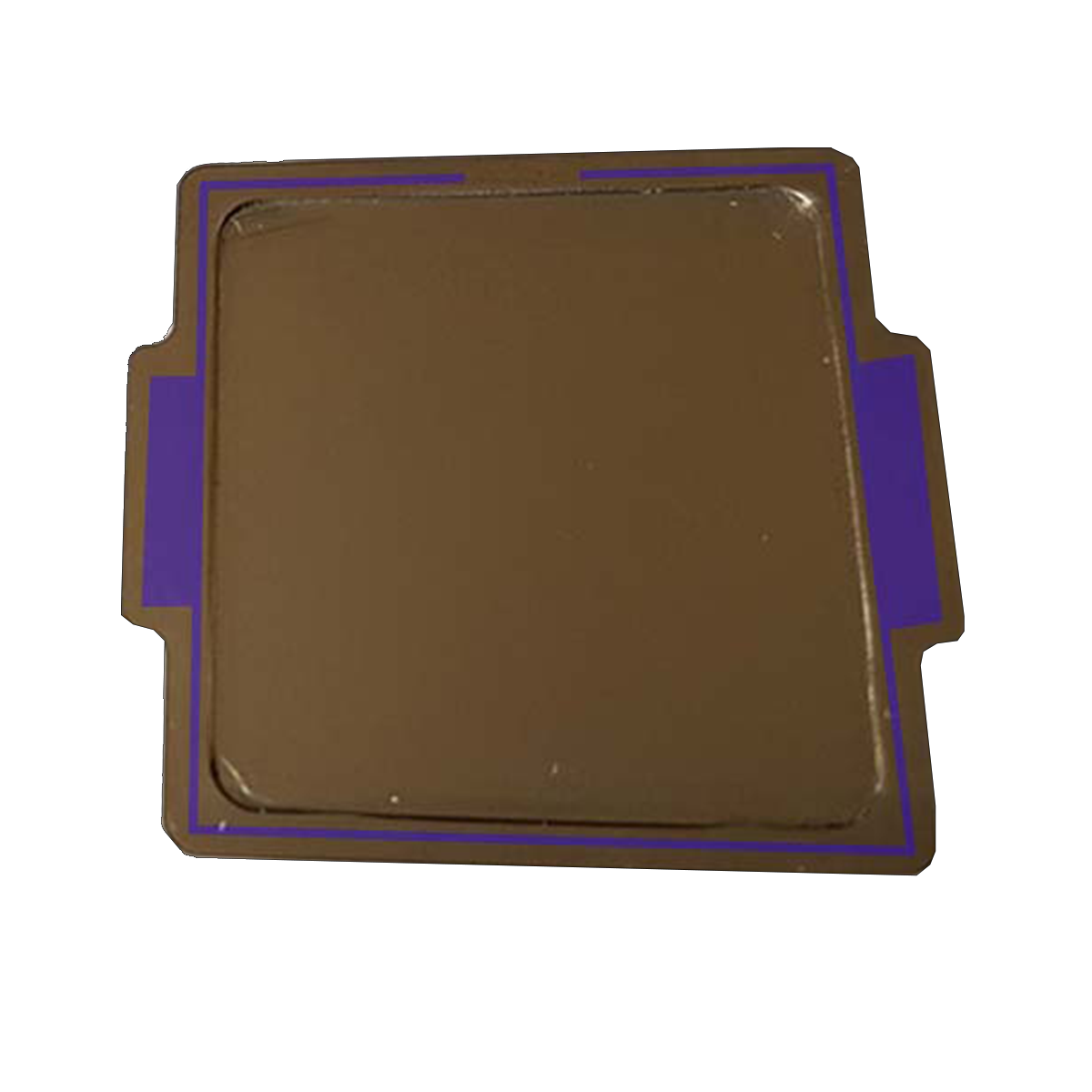
Assembling the CPU:
Now you can reassemble the CPU. I used the 3D-printed tool linked above for this. I used it as intended, but in addition to the clamp, I pressed the whole thing a little more in a small vise* than the clamp was able to do. In principle, however, many things work, even a small vise with rubber protectors should do the trick.
The whole thing has to be pressed together with force over a longer period of time so that the adhesive layer dries as thinly as possible to achieve a minimal gap between the heat spreader and the circuit board.
The crazy folks at TechPowerUp even tested this with superglue*, which hurts (irreversibly!).
The whole thing should now be set aside for a few hours to dry, rather than too little time.
Did the CPU survive?
At that point, I only had Gigabyte’s significantly undersized B250M motherboard with the appropriate 1511 socket at hand. So I had to use it again for testing, and lo and behold:
The processor is still running. Perfect.
I then aligned a 120mm fan* with the VRMs on the motherboard and let it blow at full speed while the CPU was “burned in” for hours with Prime95 Small FFTs with AVX and AVX2.
As usual, I used MX-4 from Arctic* as thermal paste between the heat spreader and the cooler.
Of course, despite the fan, the motherboard throttled the processor down to below the base clock every 10 minutes after about half an hour, but I now knew what I wanted to find out:
The processor runs stably and, even with the reused, similarly undersized Alpenföhn Sella, is easily 20 °C cooler than before. Even under these very unfavorable circumstances, there is no longer any thermal throttling of the CPU!
I read this several times during my research; temperature reductions of 10 to 30 °C (when overclocking) are supposed to be possible. But seeing it live was something else entirely—I had never seen such an extreme improvement before and have never seen it again since, and since more modern processors inherently reach their thermal and performance limits, I probably never will again.
What are you doing, Intel?
The real insight is that Intel (intentionally?) used cheaper thermal paste instead of more expensive indium solder in production to either limit these CPUs or to achieve the effect over time that they become hotter and slower because the thermal paste dries out and will probably even lose contact between the die and heat spreader in some cases. Since “Ivy Bridge,” thermal paste has been used instead of solder, up to and including “Kaby Lake,” the generation from which this i7-7700K also originates.
The FAT and SLIM models of Sony’s Playstation 3 were technically given a best-before date in the same way (thermal paste between the heat spreader and die on the CPU and GPU). The Super Slim is then Direct-Die, presumably for space reasons.
This project was a complete success, and now suitable hardware is being sought to adequately overclock this CPU.