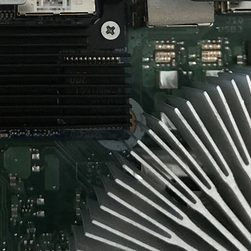
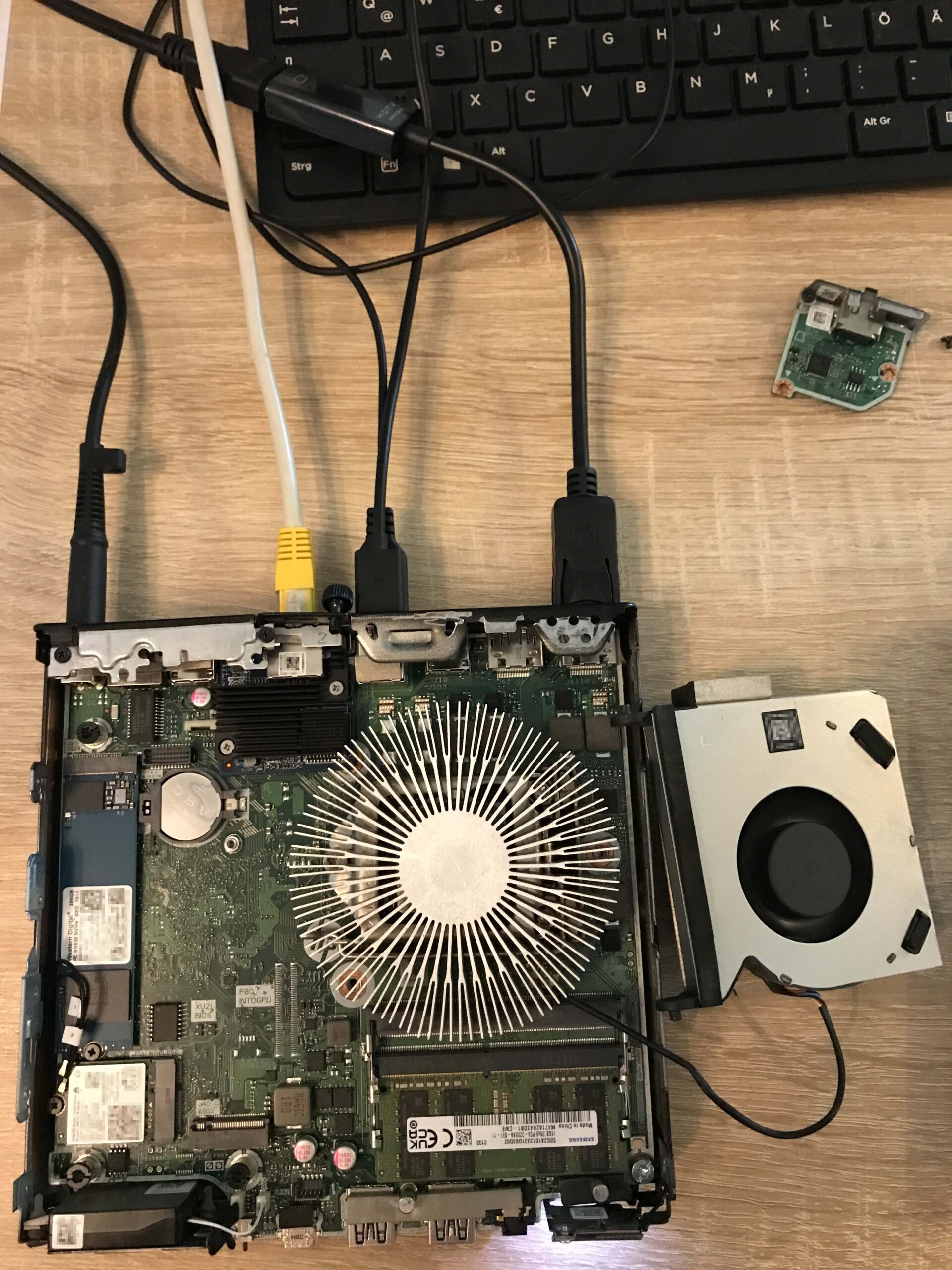
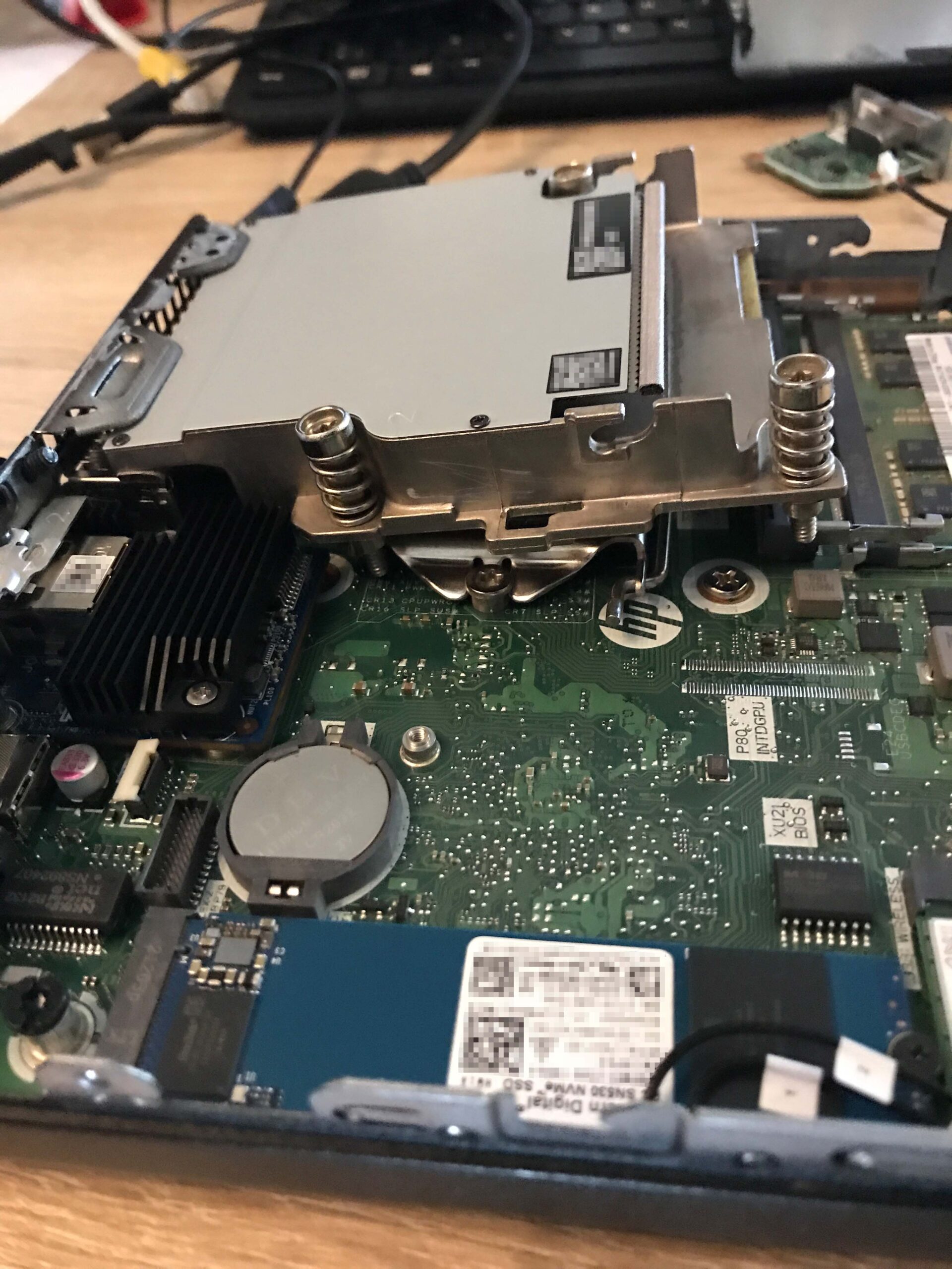
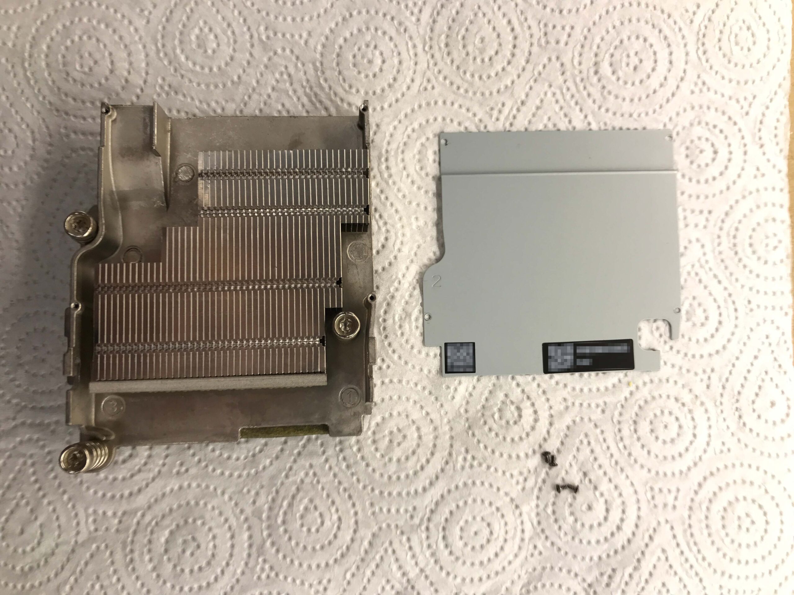
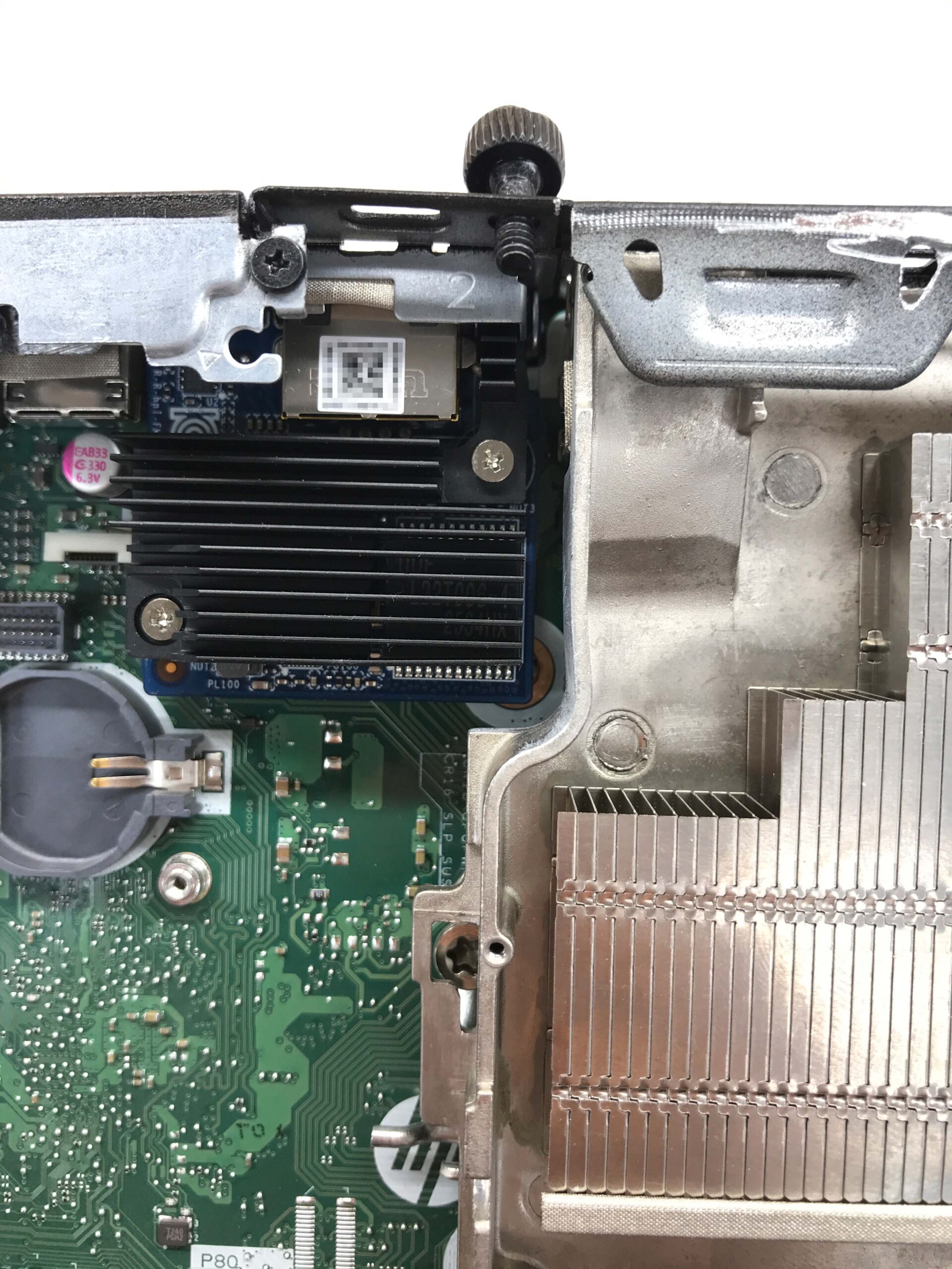
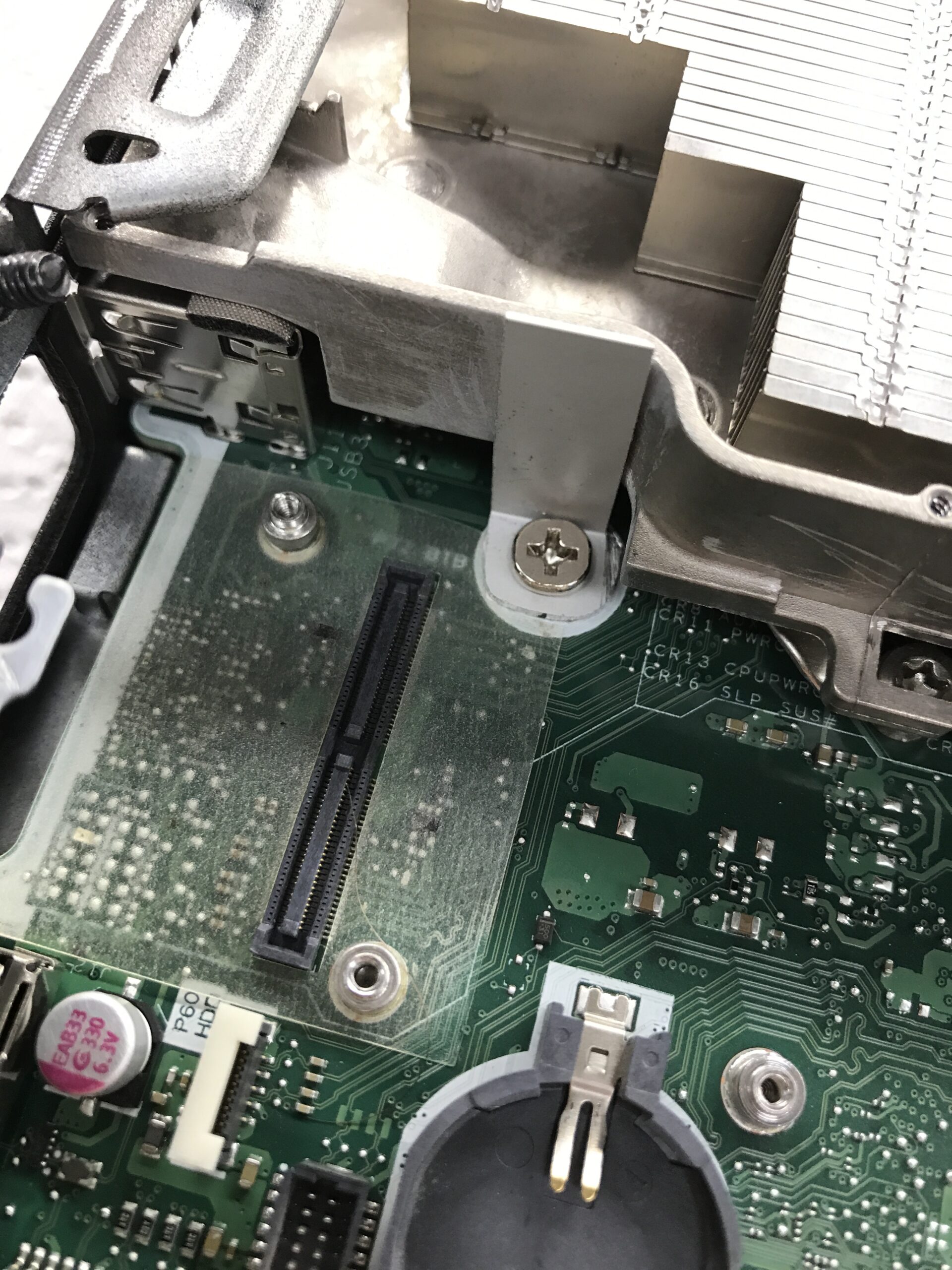
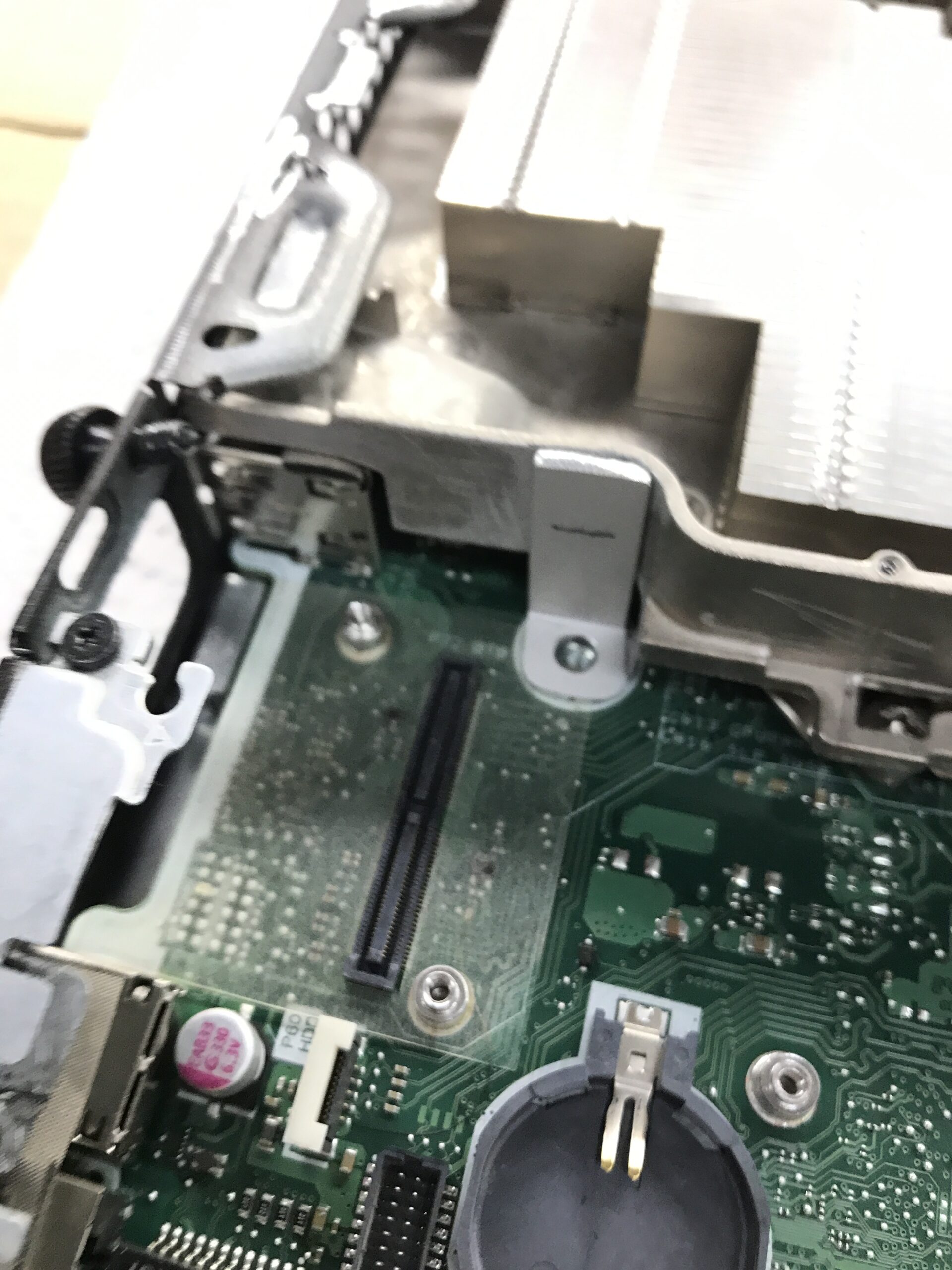
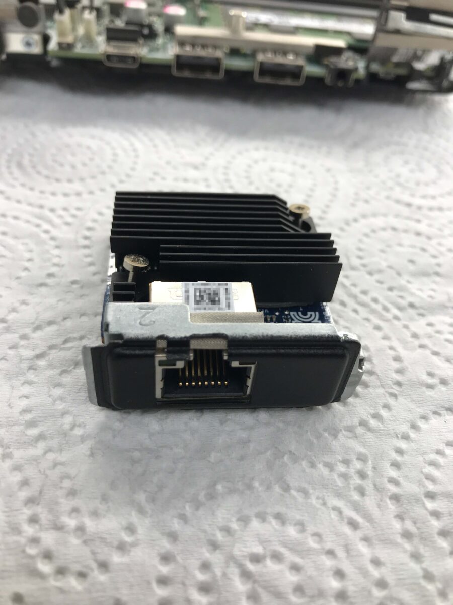
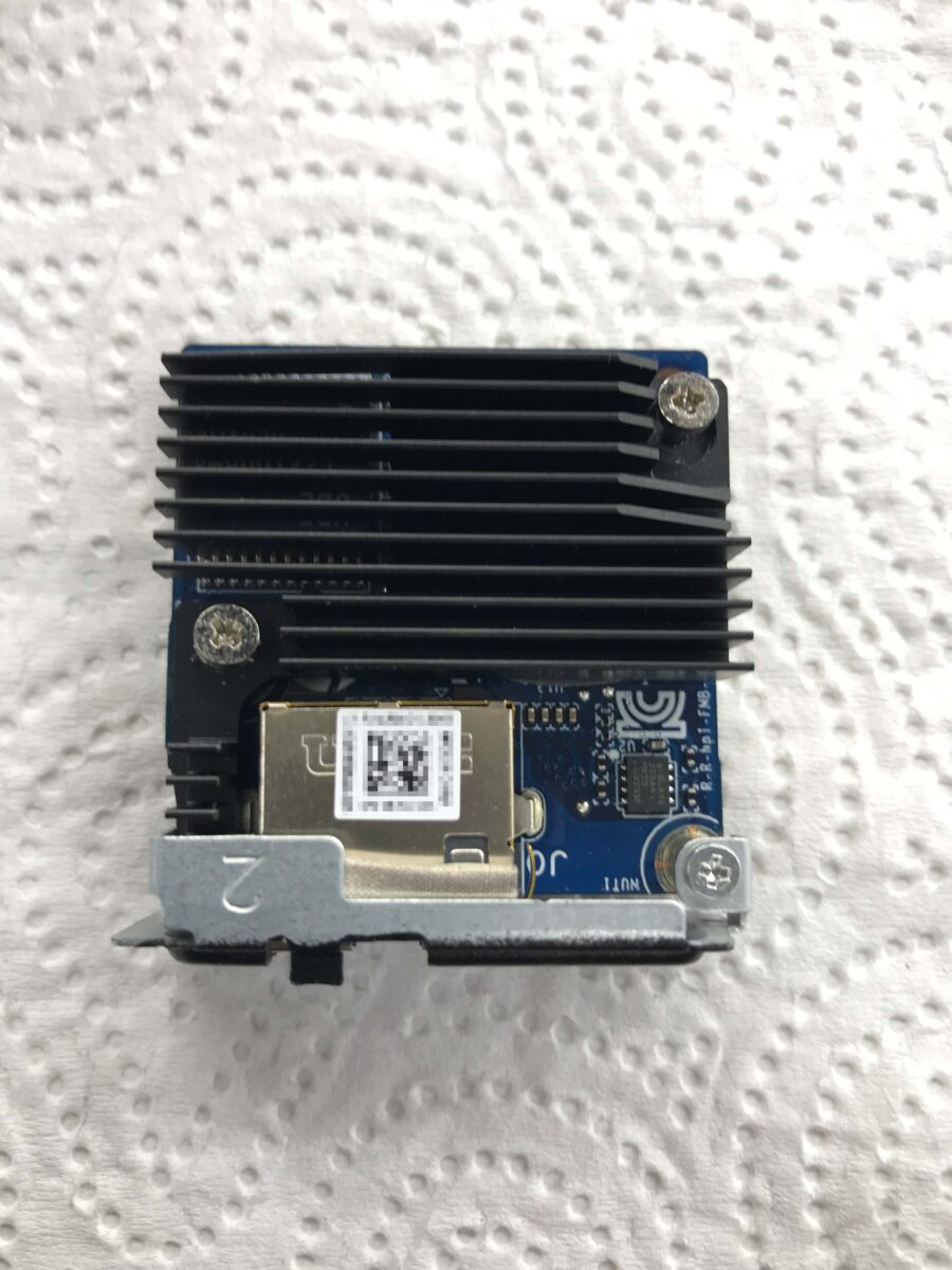
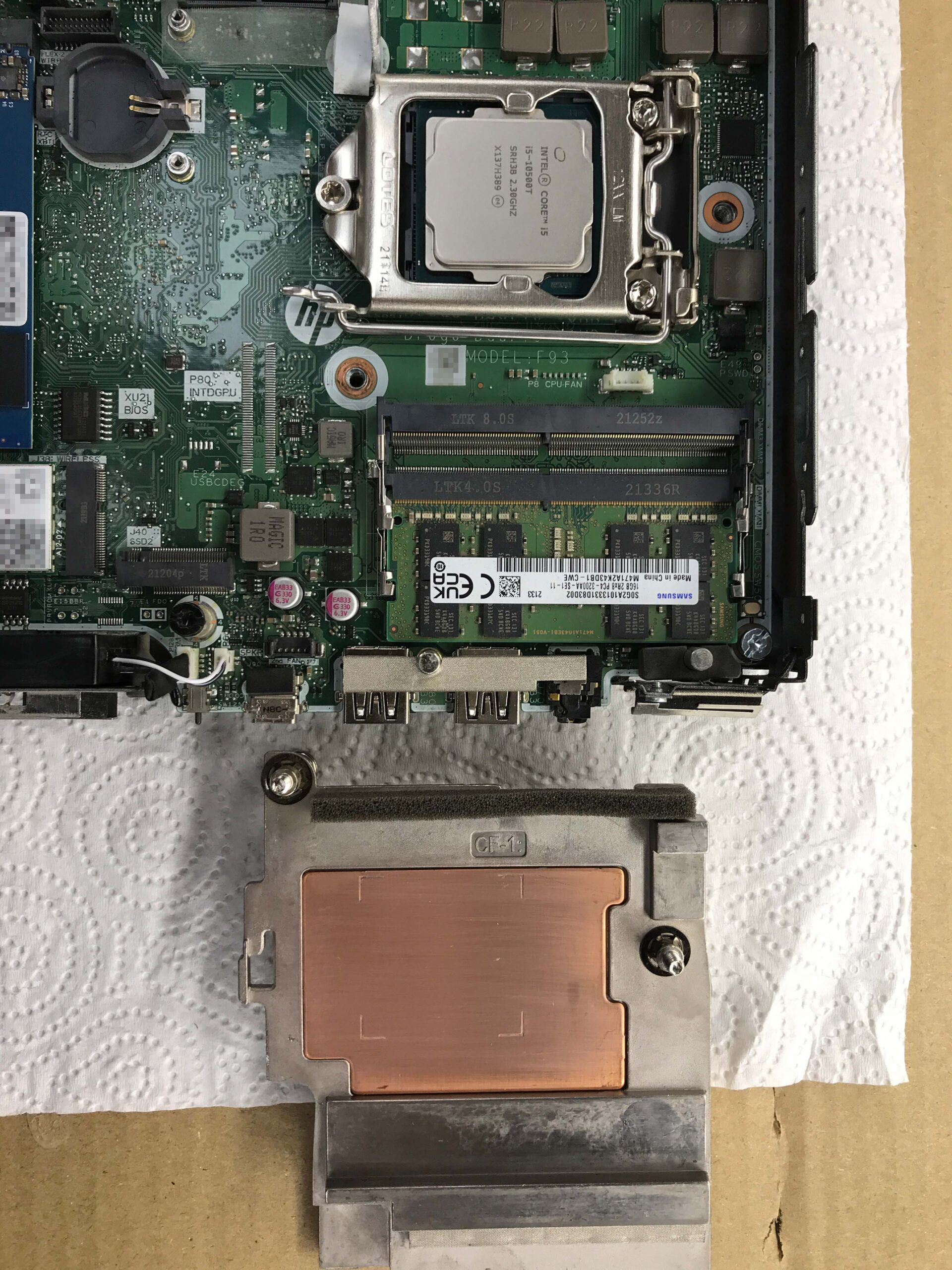
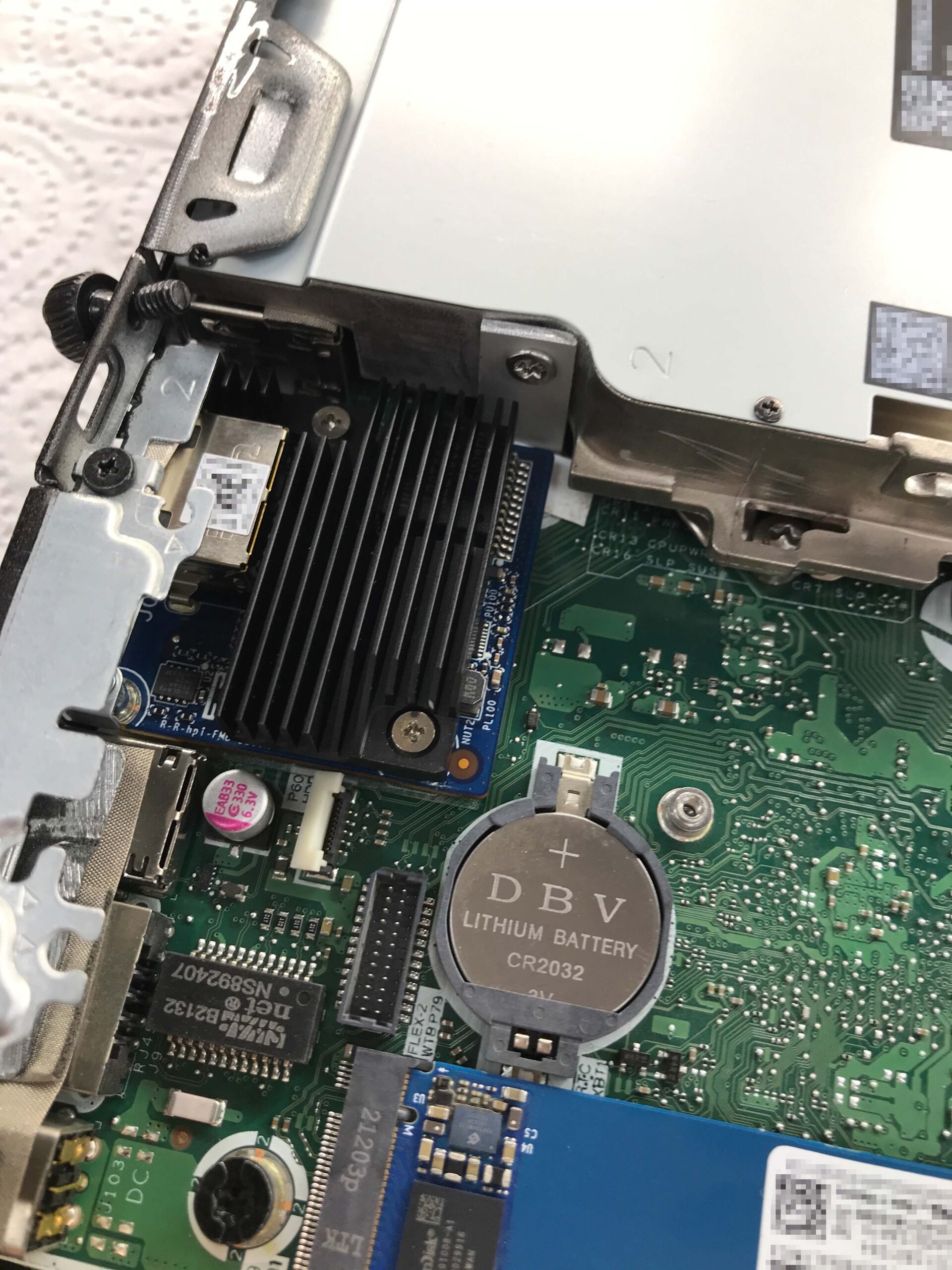
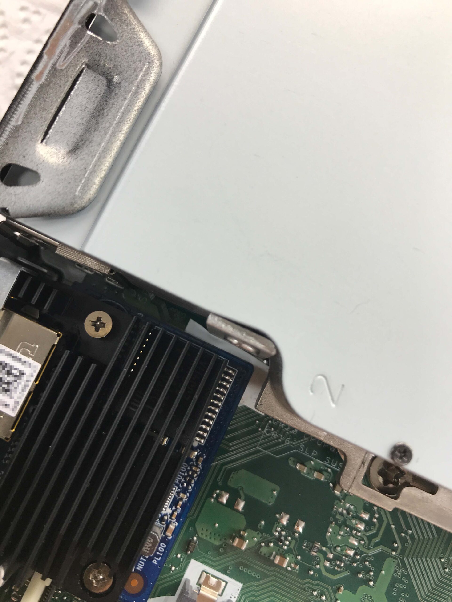
First and foremost, I had to make sure that the module actually worked, both electrically and in terms of software. I’ve read in several places online that there are indeed models (e.g. the ProDesk series) where the module physically fits but doesn’t work on the UEFI side because the necessary drivers don’t seem to be integrated there. To address this, I temporarily replaced the CPU cooler with an old Intel cooler, with some thermal paste in between. This allows the module to fit:

When offline, the network adapter is recognized as such, and Windows automatically installs the appropriate driver once an Internet connection is established. However, the module should also be recognized and function properly with the driver directly from Marvell; moreover, the driver version from Marvell is always more recent (Marvell Public Drivers -> Windows -> AQC113):
Download the drivers from Marvell
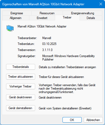
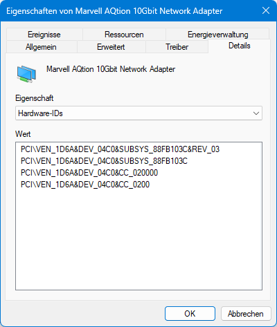
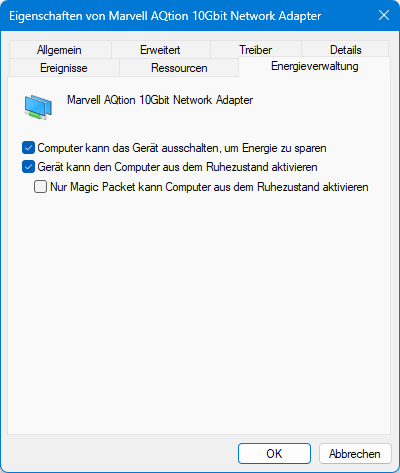
Device Manager
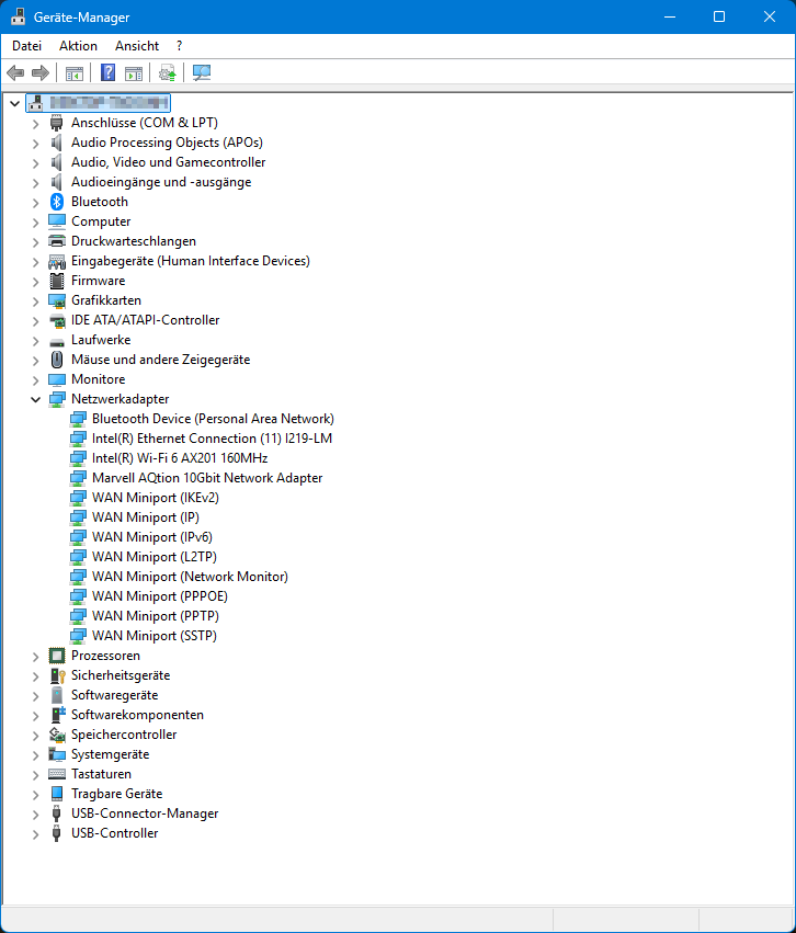
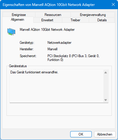
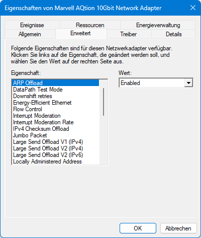
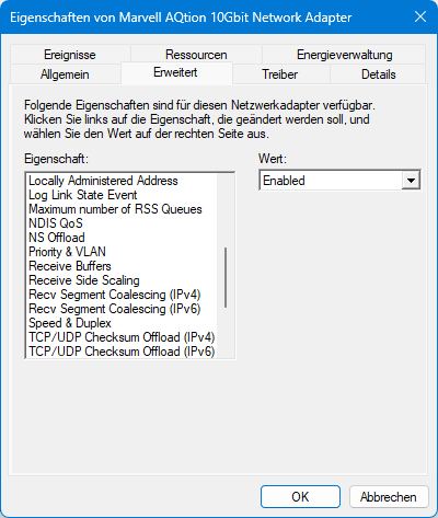
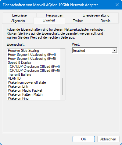
Once everything has been installed correctly, you can check in Device Manager to see if everything has been configured or recognized as expected:
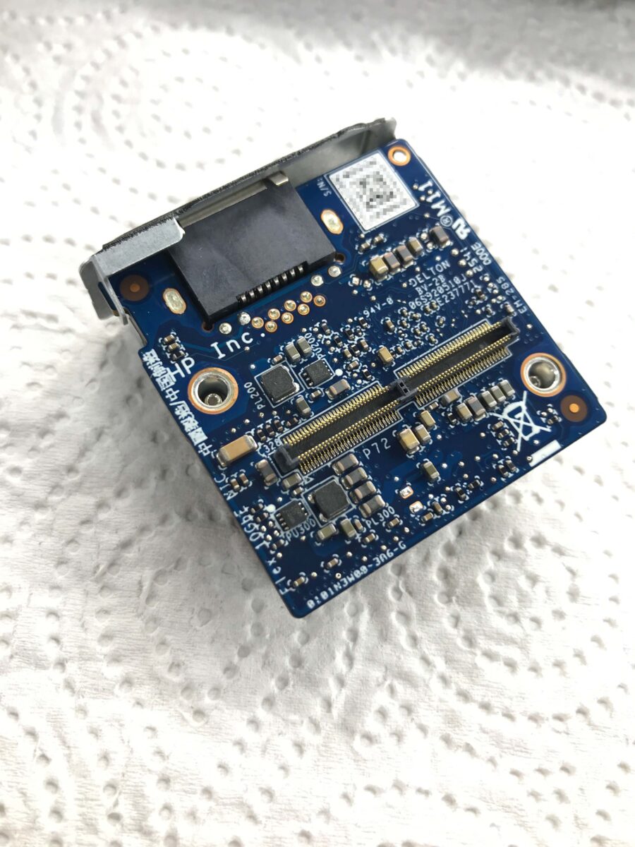
You can also learn a lot about the module using HWiNFO:
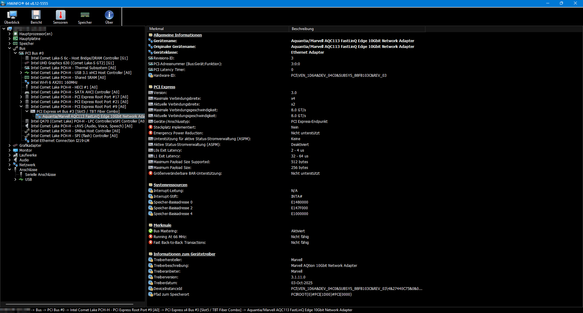
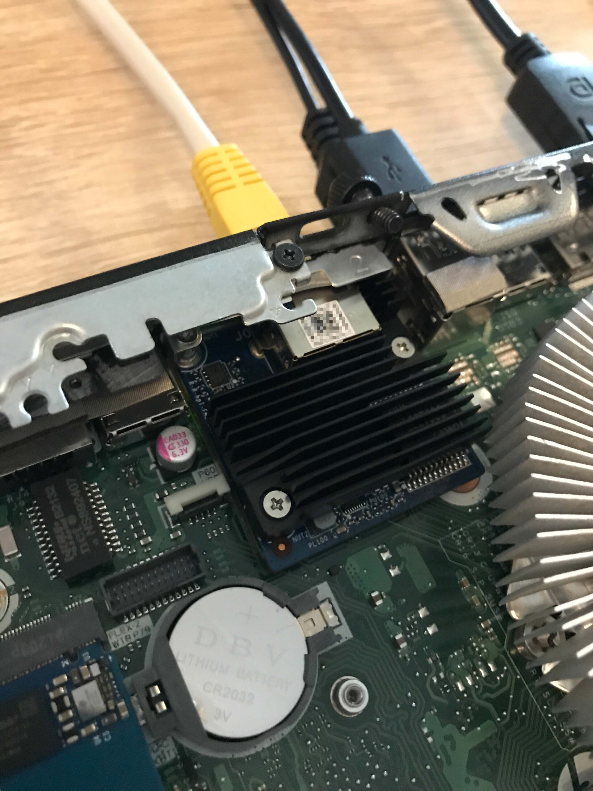
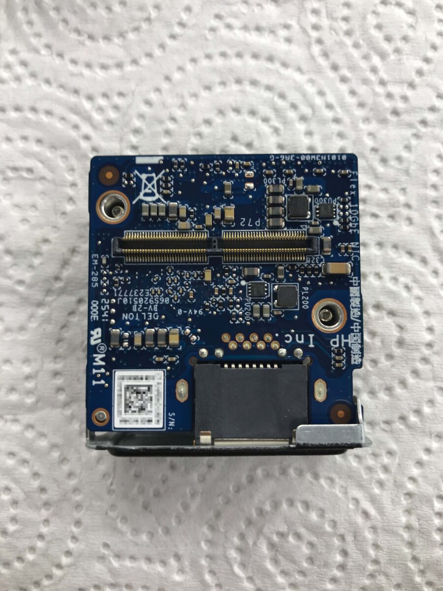
The module is connected internally via the FlexIO v2’s proprietary slot using two PCI Express 3.0 lanes, which should easily support the full 10 Gbps (one PCIe 3.0 lane theoretically provides 8 GT/s, so two lanes provide 16 GT/s. This theoretically corresponds to 1.969 GB/s, whereas 10 GbE can transfer a maximum of approximately 1.25 GB/s).
In summary, it appears that everything is functioning properly at the electrical and software levels. It is therefore truly “only” a mechanical issue that prevents the revised, newer module from fitting into the Mini PCs. A completely baffling decision on HP’s part.
Mechanical adjustments
On closer inspection, it should be possible to adapt the mounting point. Ideally, this would be a CNC-machined part that incorporates the factory-installed spring pressure beneath the screw to ensure the cooler continues to apply the necessary contact pressure to the CPU. However, I wanted to resolve the issue practically and quickly, so I built an adapter out of an aluminum angle profile, right on the actual component.
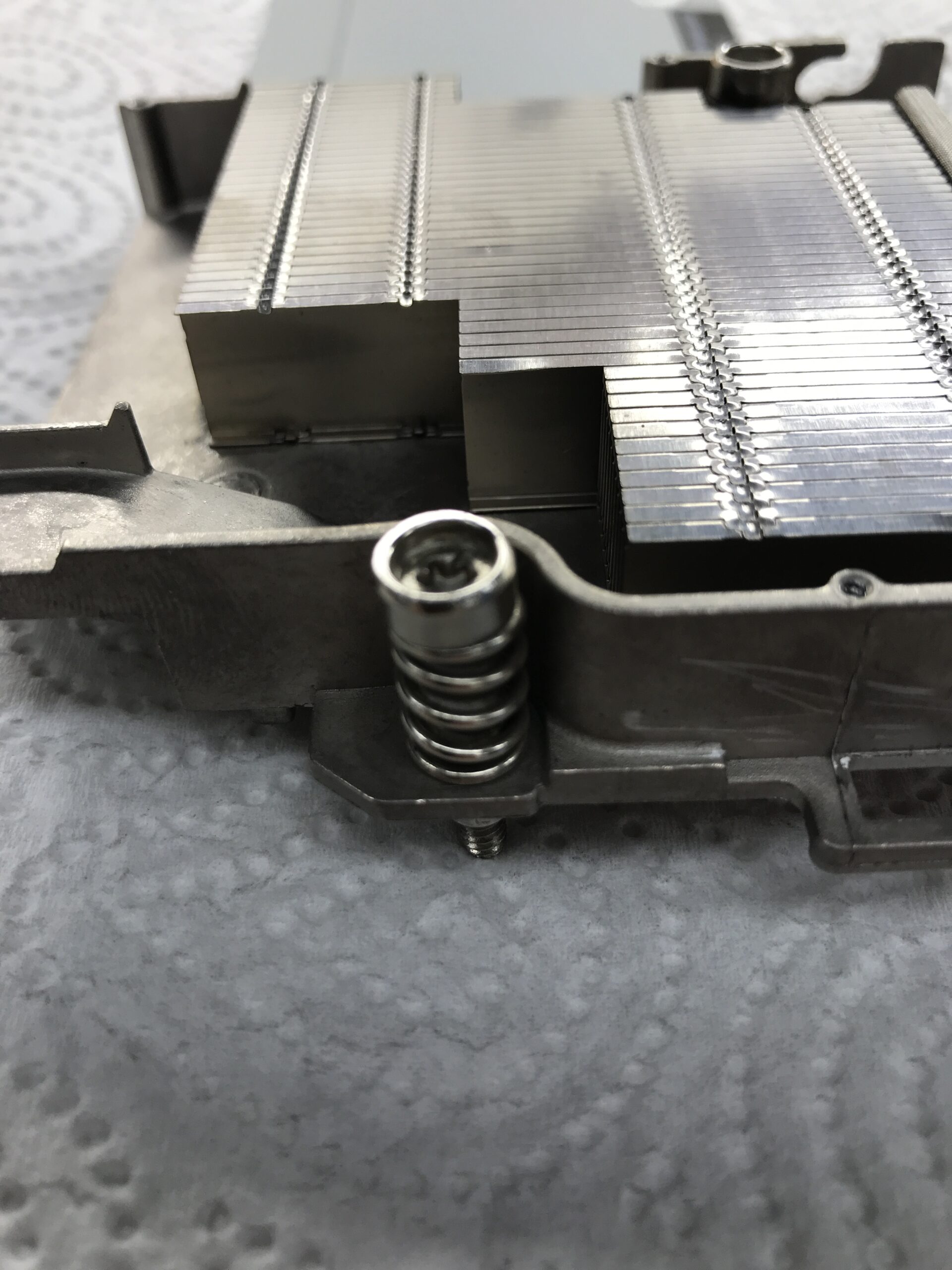
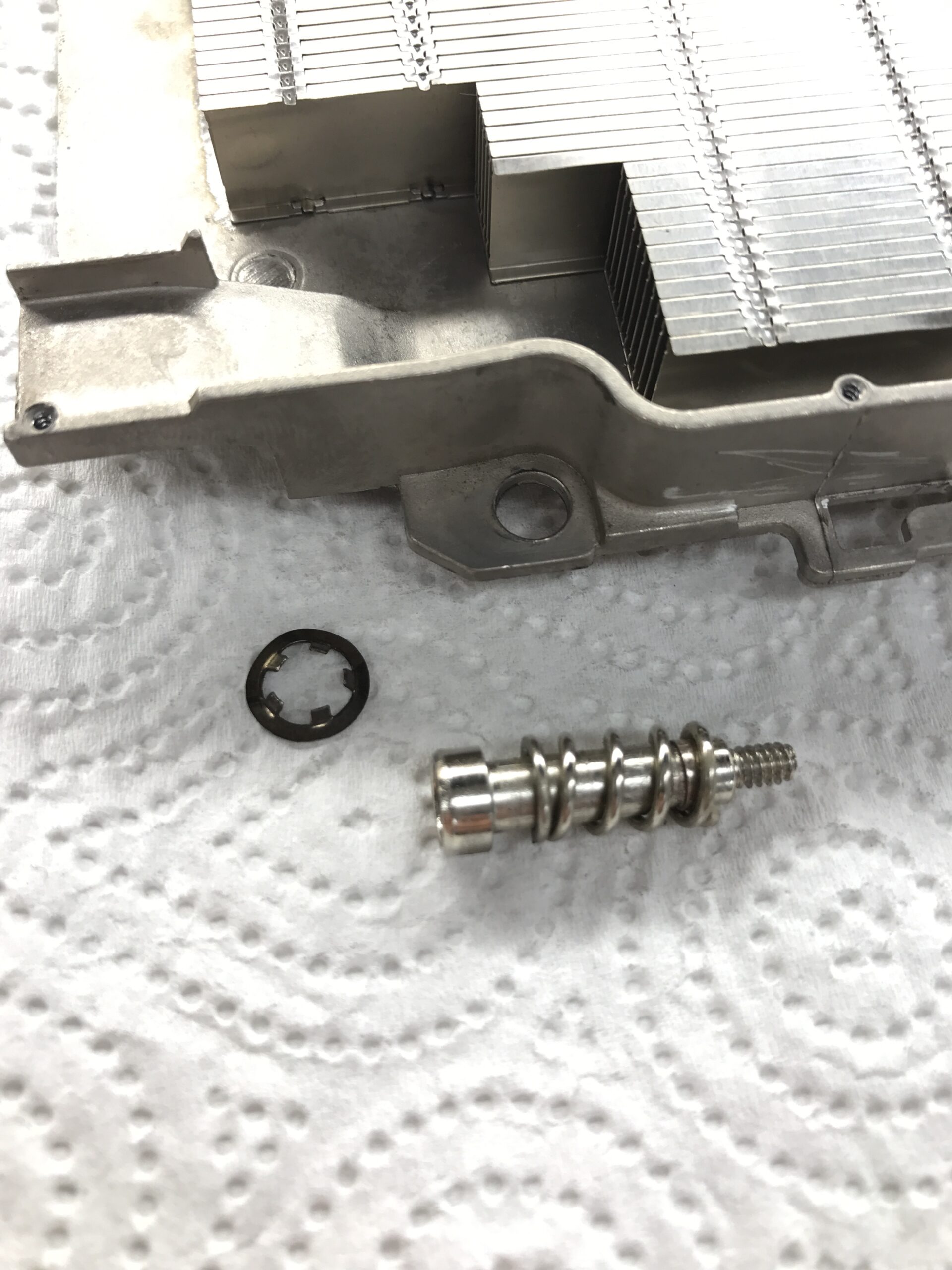
First, the cooler needs to be made mountable at all; to do this, I first took stock of what was possible:
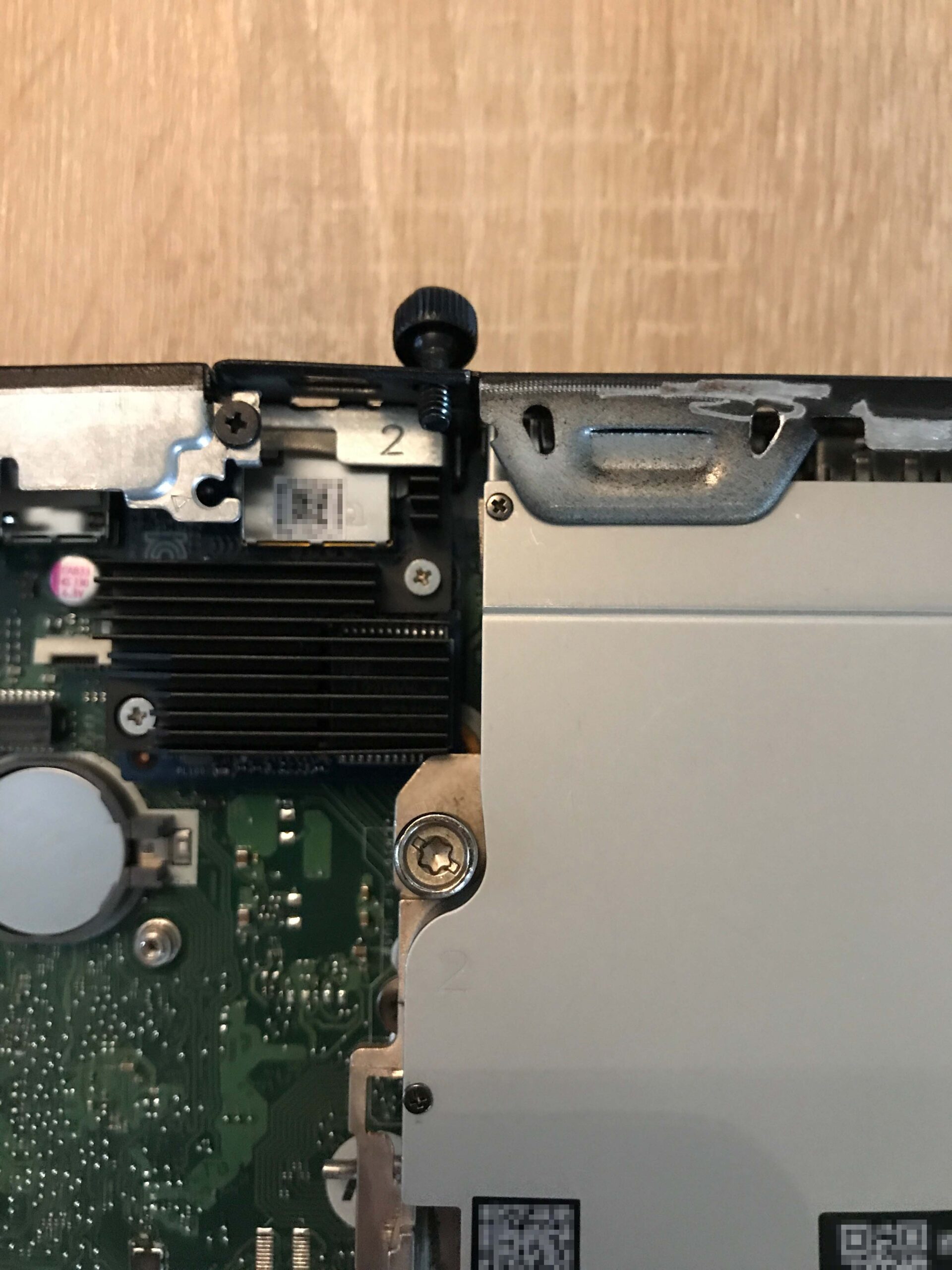
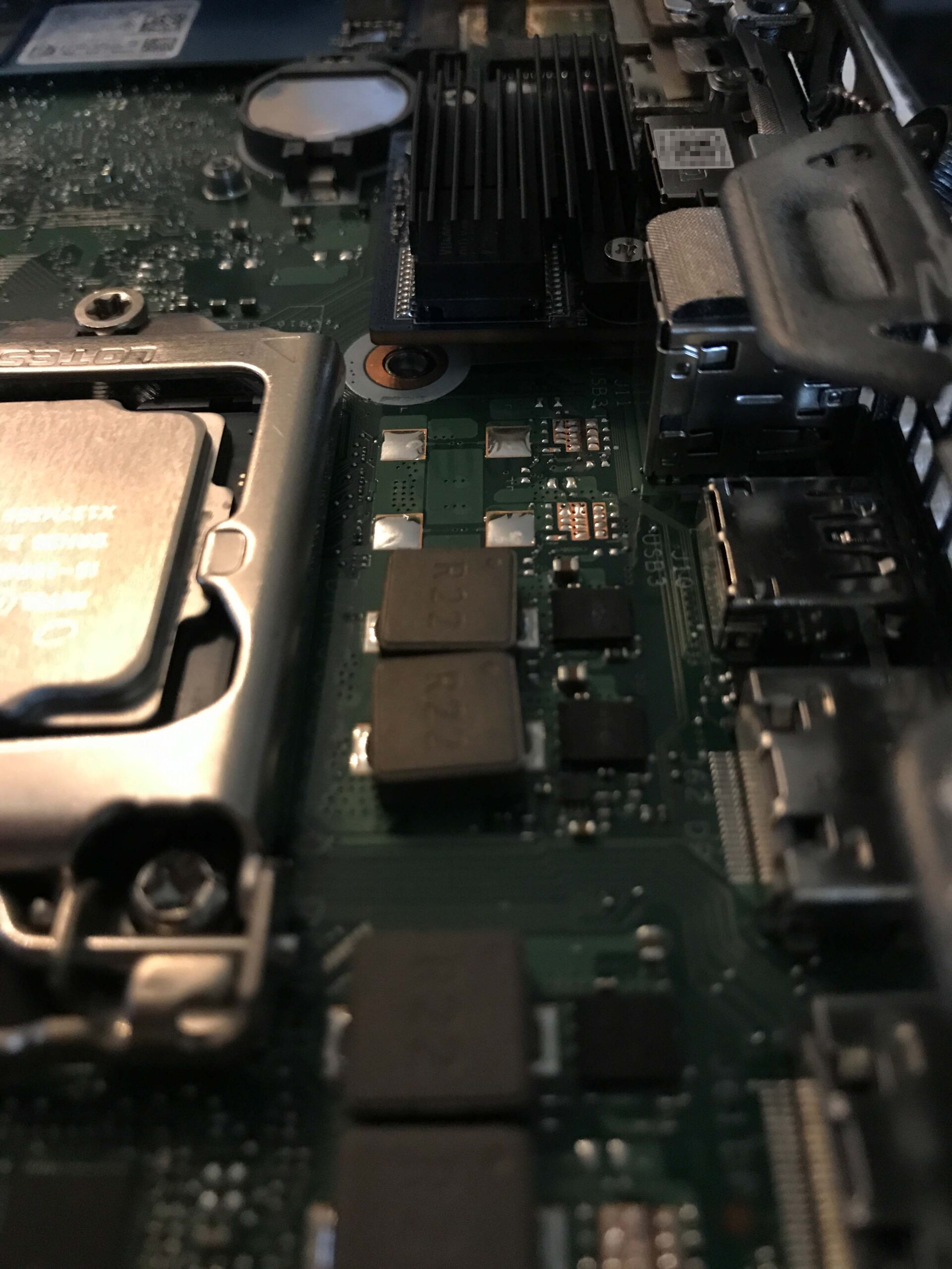
The third bolt connection has to go; unfortunately, there’s no way around it. There isn’t much room, but at least there’s some.
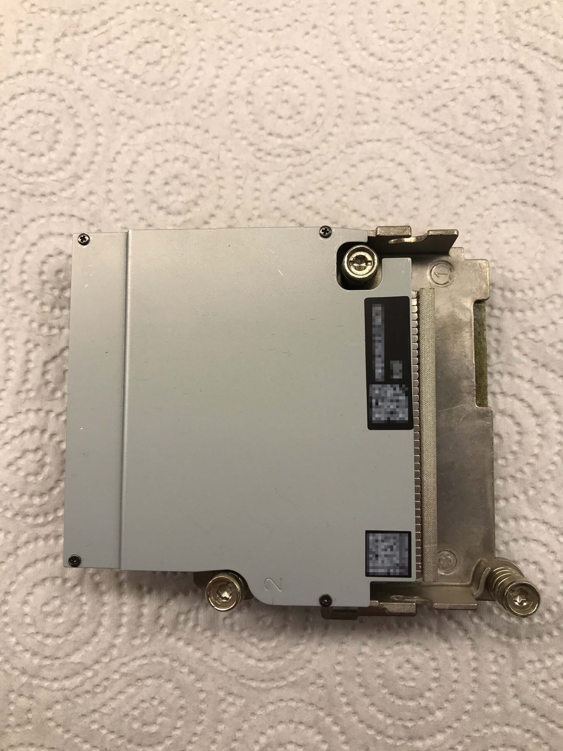
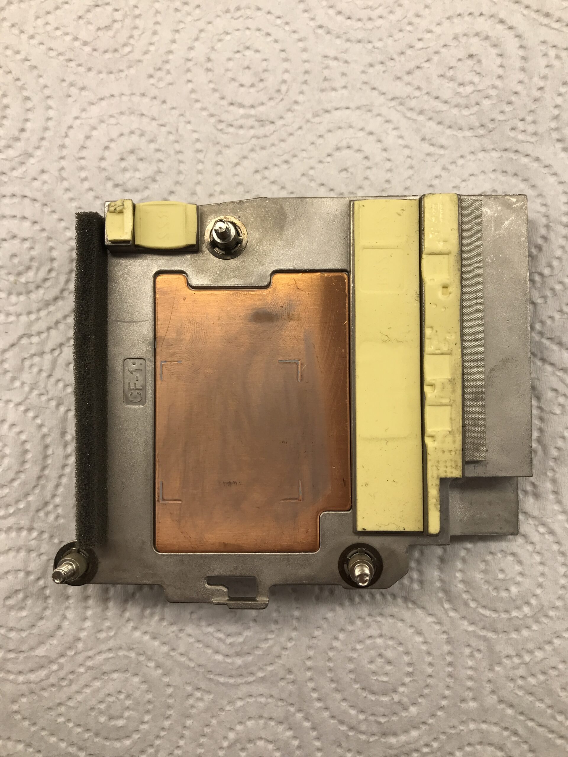
Cooler modification
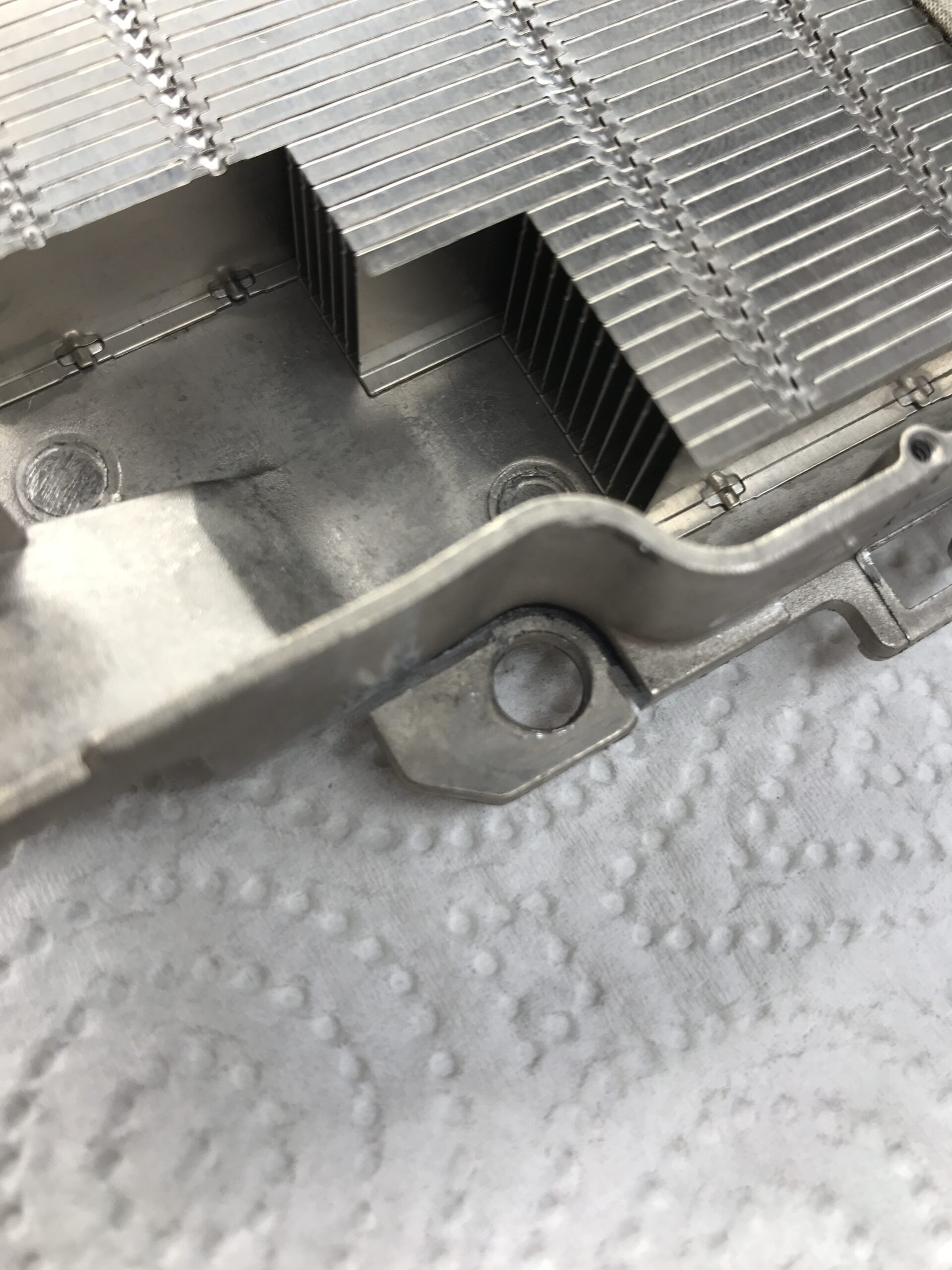
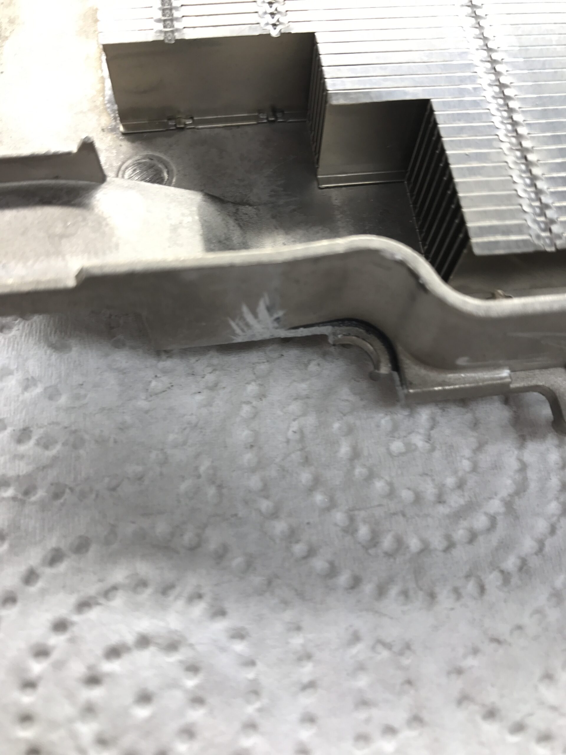
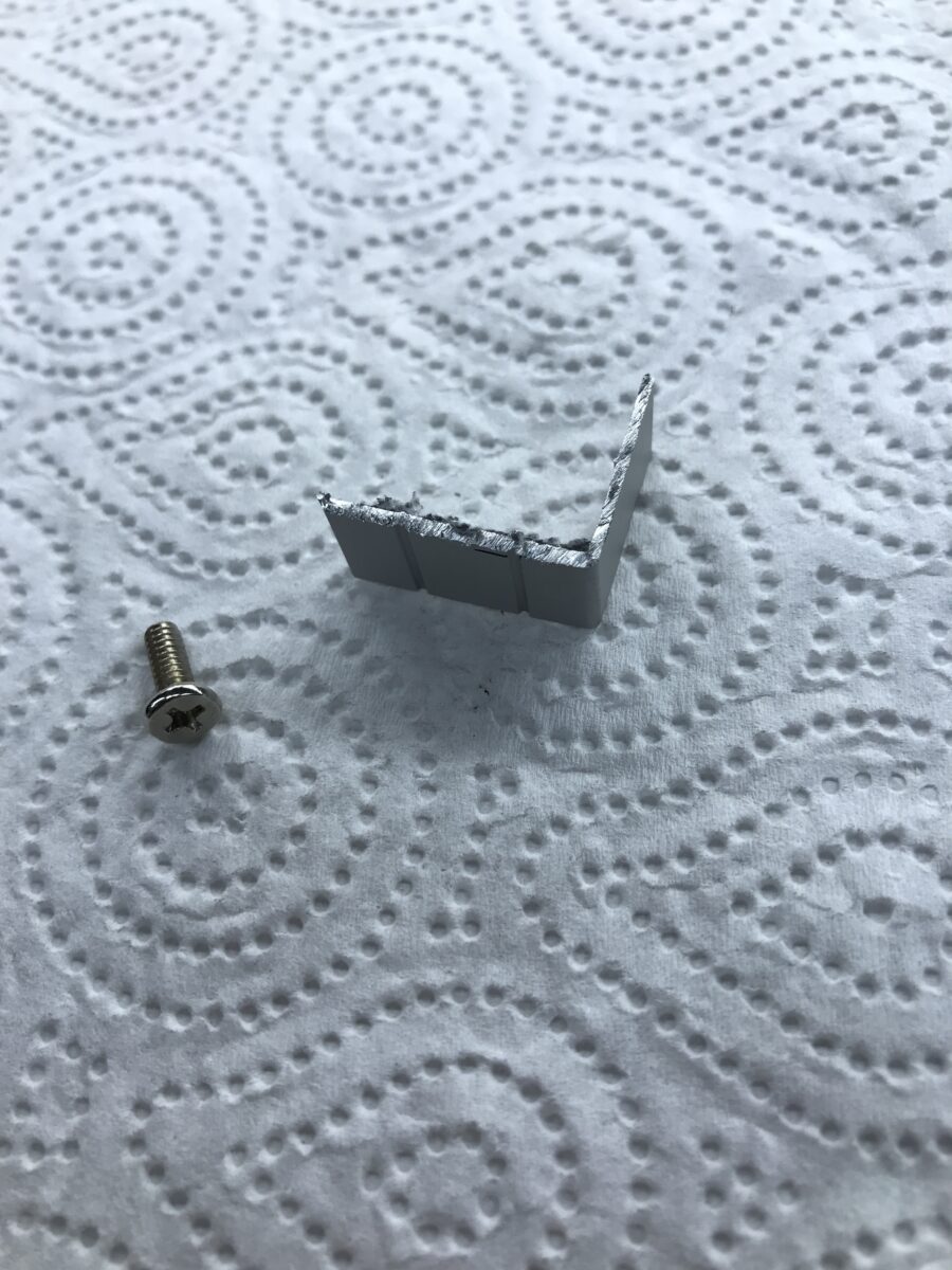
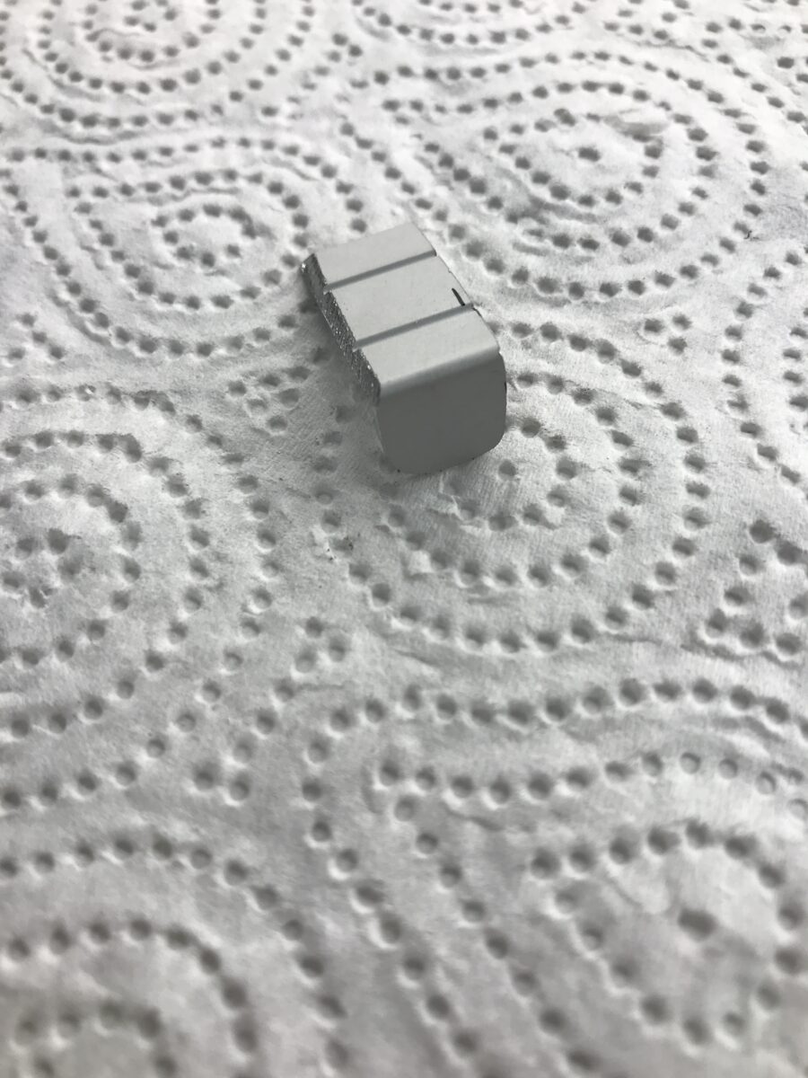
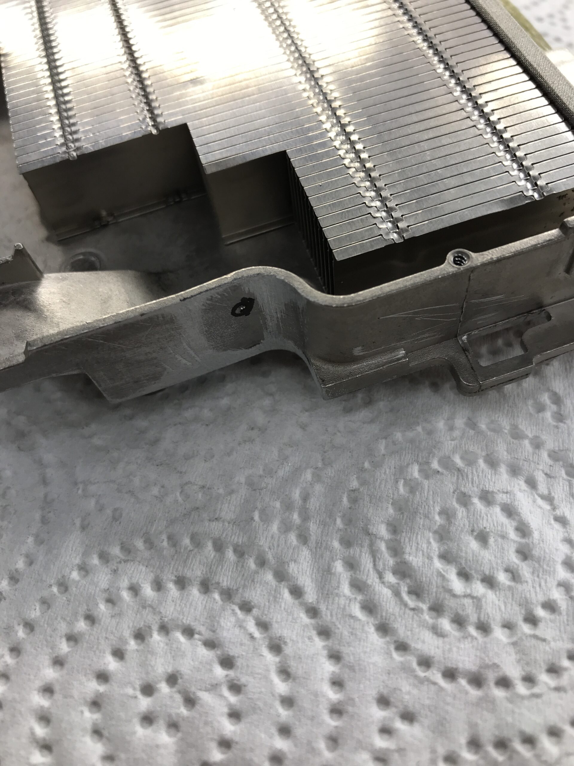
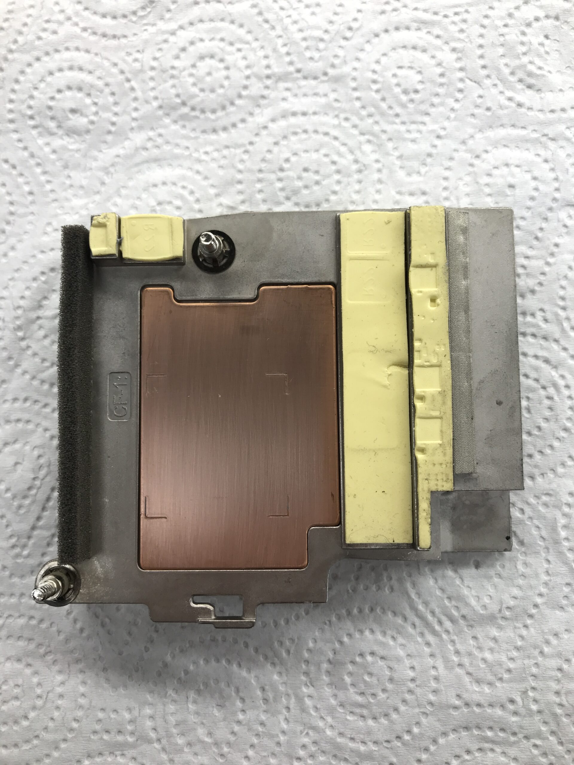
First, I removed the thermal pads to prevent metal shavings from getting inside them. Next, I unscrewed the tinplate cover of the cooler (PH0) to see what the inside looked like. Then I modified the “corner” to fit:
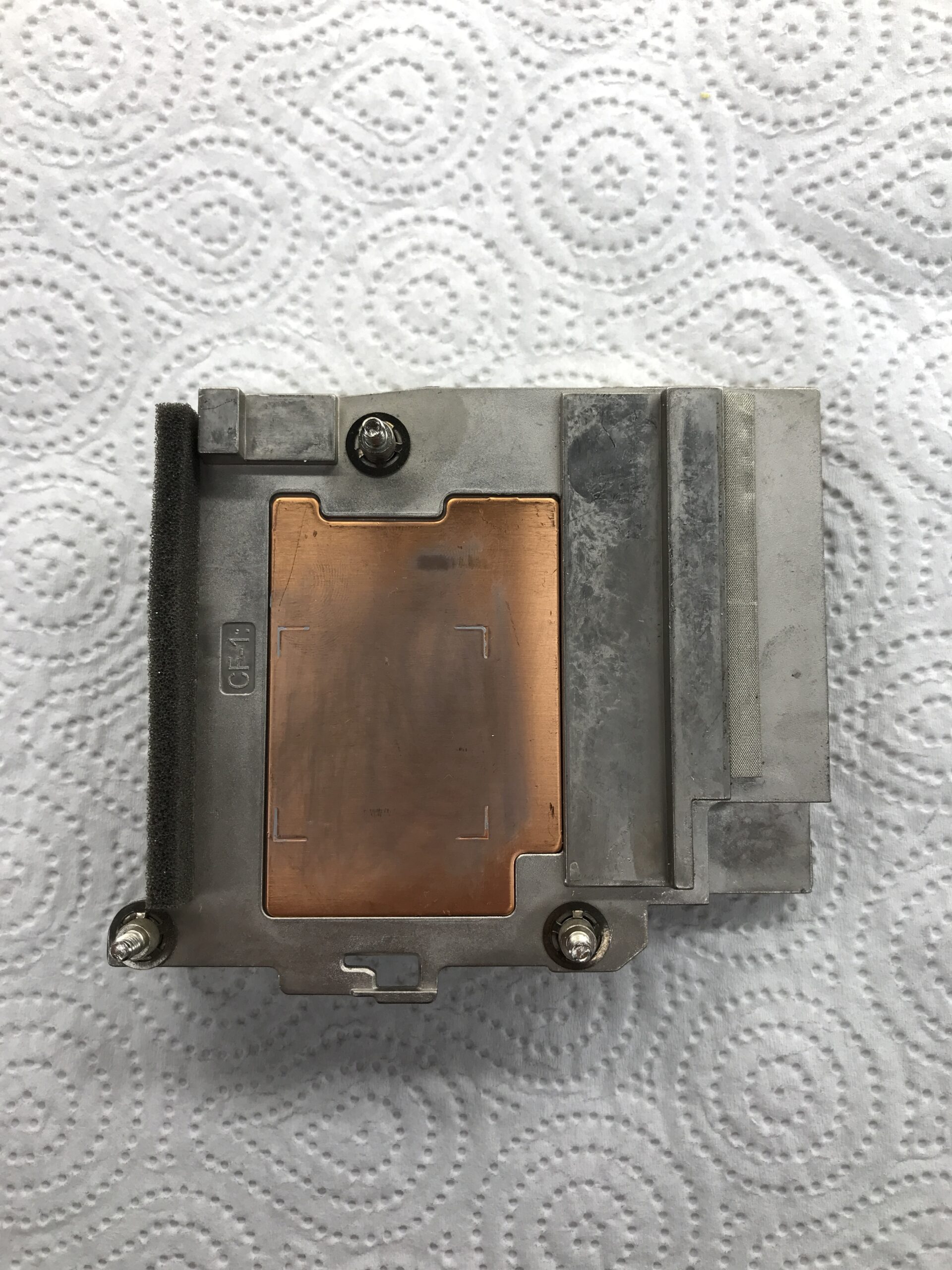
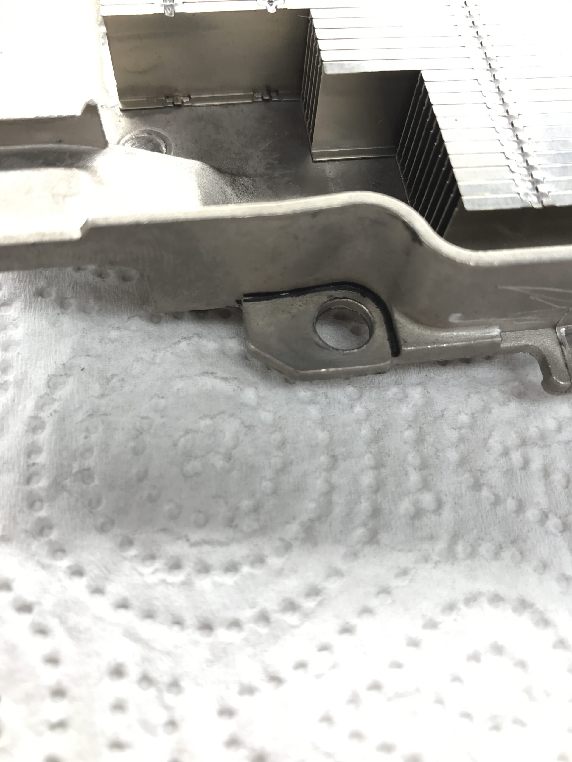
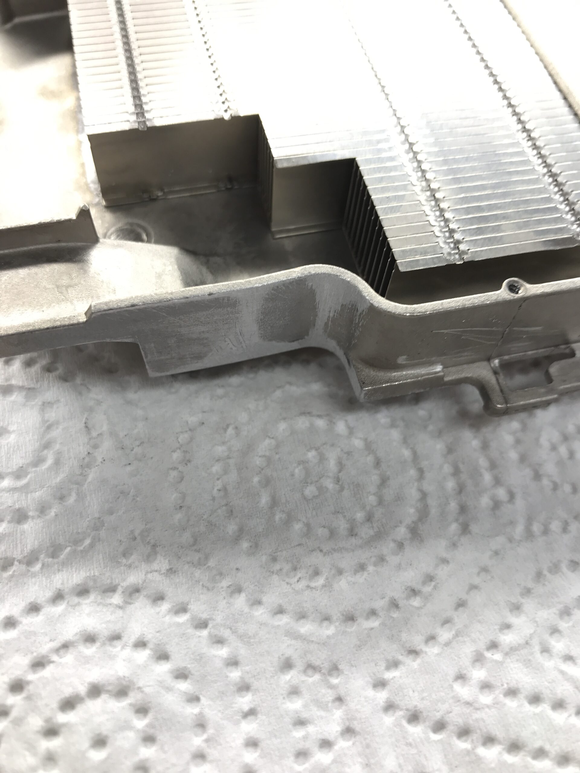
Now, at least, the cooler and the network module can be placed in the right spot:
Build a mount
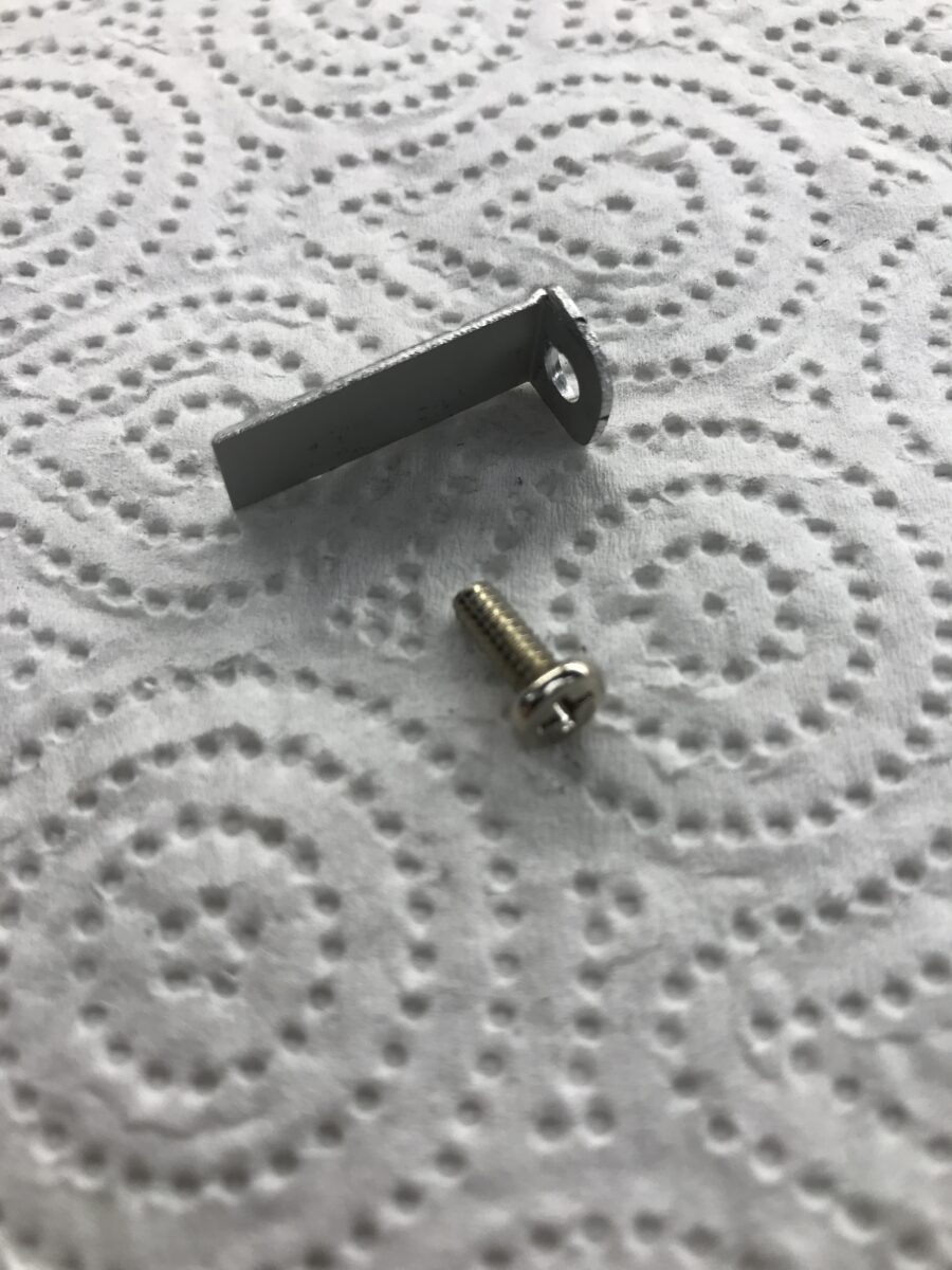
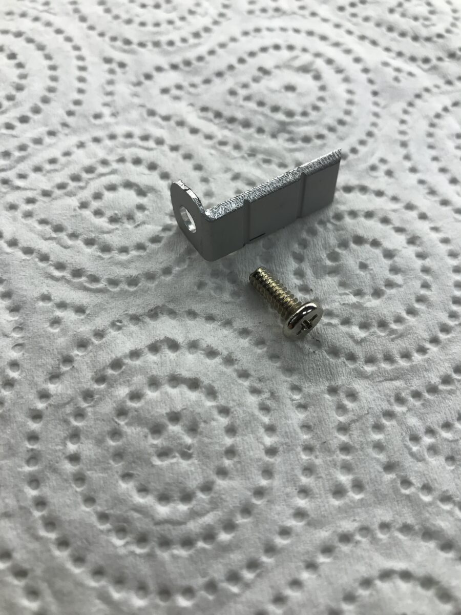
I used a leftover piece of an aluminum angle profile and modified it accordingly. I had a suitable screw with the “UNC 6#-32” inch thread – which is (unfortunately) common in the IT sector – in my parts stash. This is the same thread used, for example, on the side mounting holes of 3.5-inch hard drives:
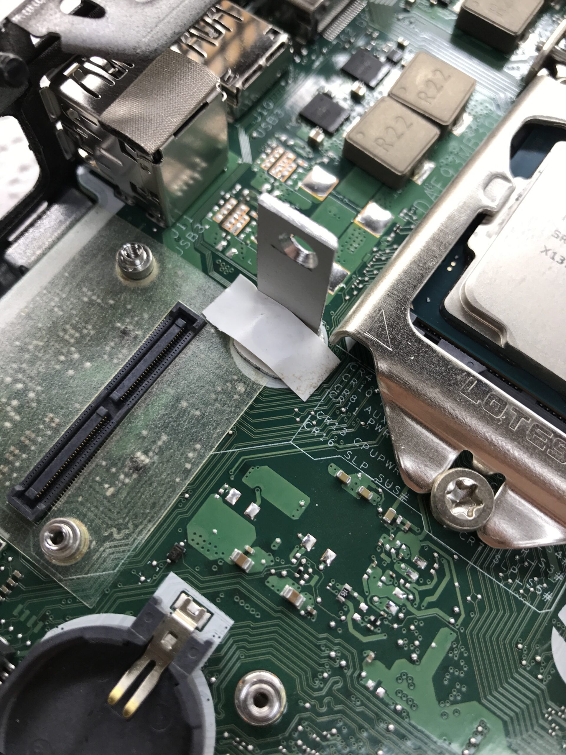
To determine the position of the second hole for mounting the cooler, I temporarily screwed the component into the mini PC. On the underside, where the bracket touches the circuit board, I used PVC electrical tape to provide insulation and protection:
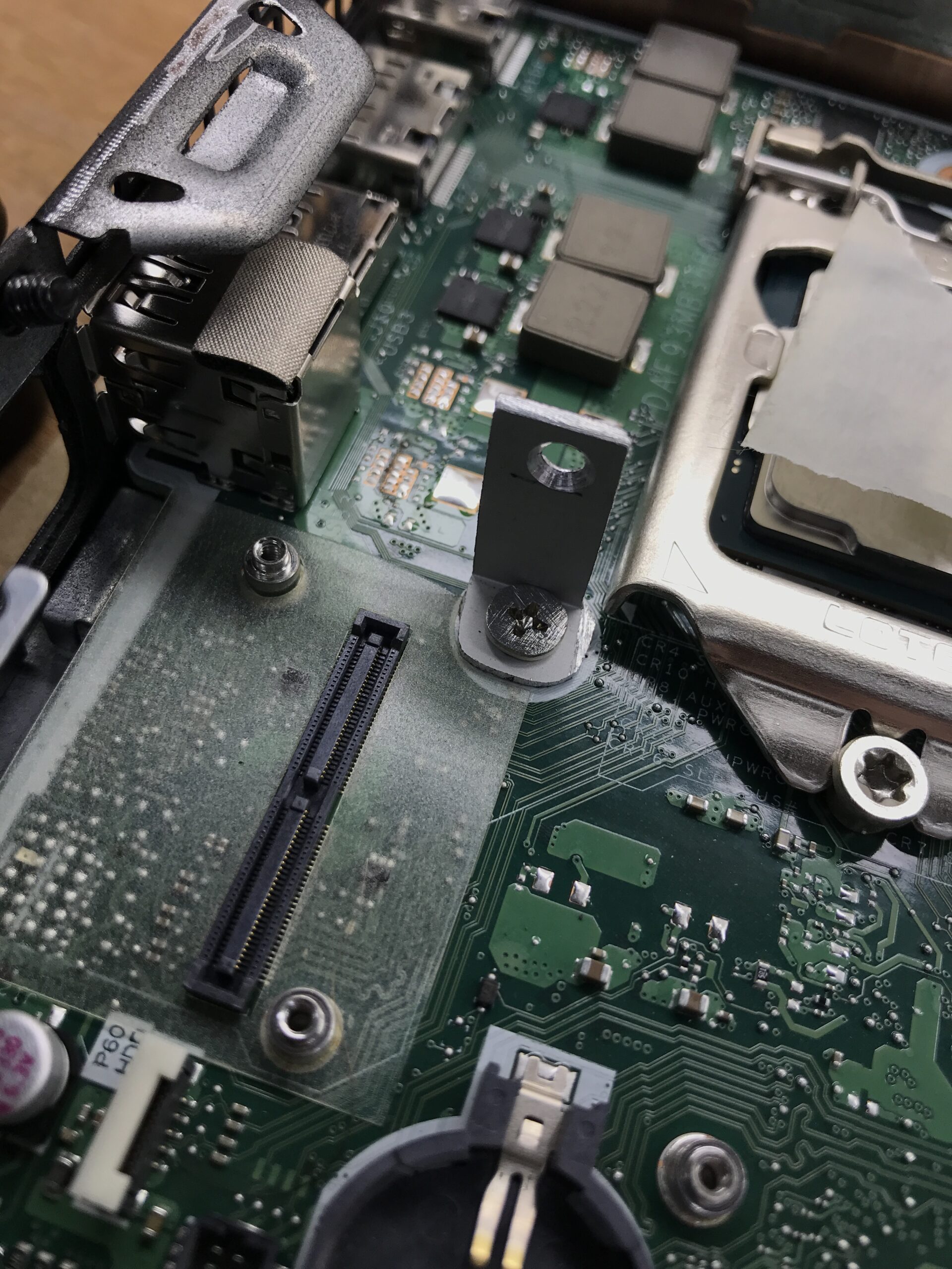
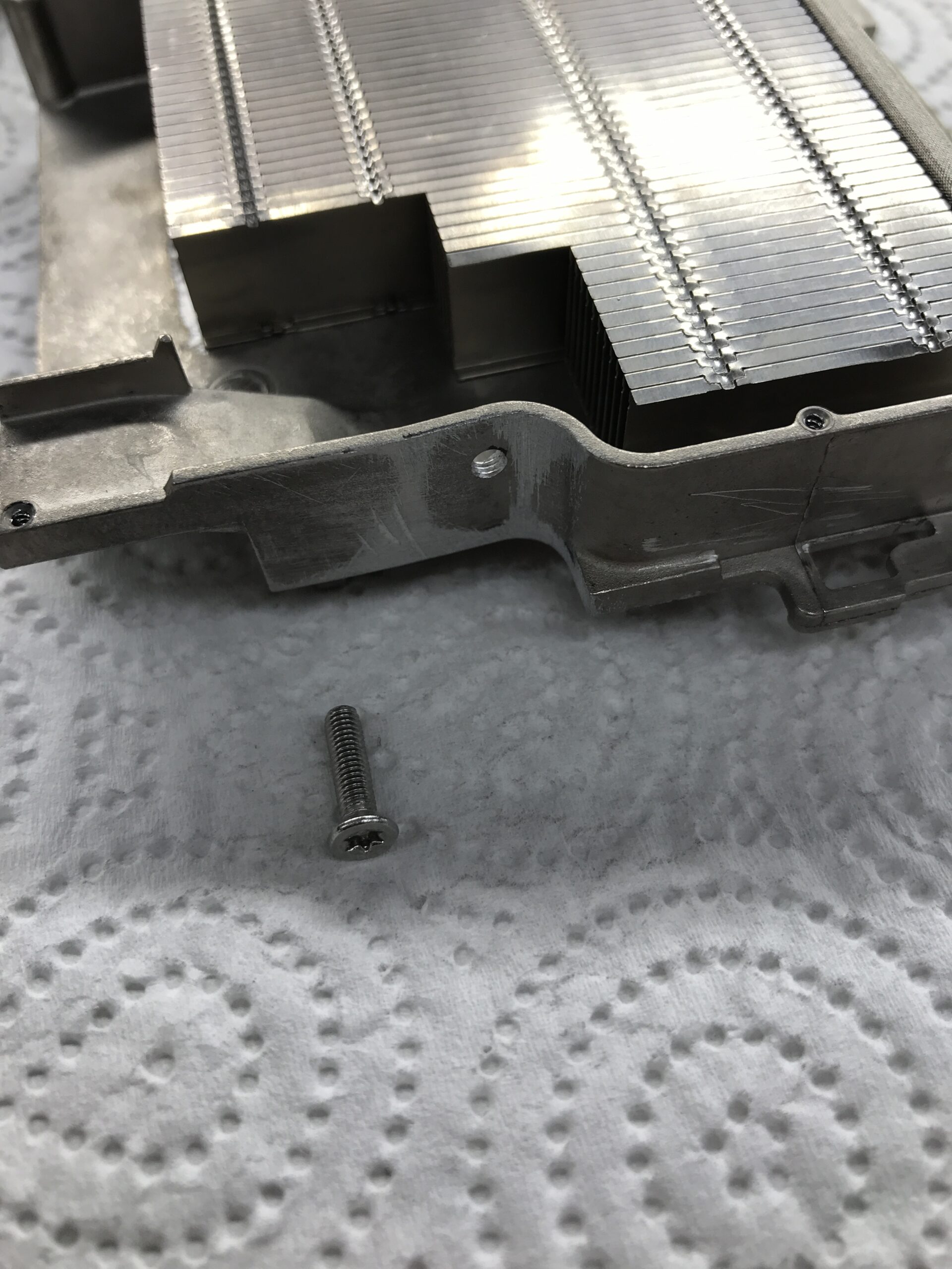
The Torx screw facing the cooler is an M3 stainless steel countersunk screw, designed to apply at least some pressure to the processor via the countersunk head. I felt that securing it using the slotted hole in the bracket and a pan-head screw was too “unreliable” – if it slips, nothing will hold it in place. I also filed down the UNC screw at the original mounting point, since the ill-fitting module directly above the screw is unfortunately also full of components from below:
Now I was able to put everything back together and run some initial tests. I used Arctic MX-4 as the thermal interface material to check whether the modification actually works or if the cooler fits so poorly that I need to build a second, more stable version. I applied a layer of white PVC electrical tape to the filed-down screw head, just as I did on the underside of the bracket; a standard sheet of printer paper fits just barely between the SMD components and the PVC. It works, but it’s still very tight:
Now we need to determine whether the cooling capacity is still sufficient so that we can then update the network controller’s firmware first.